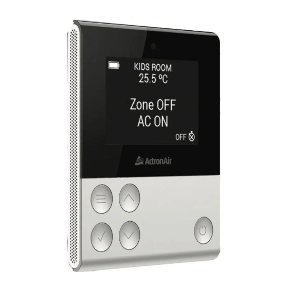
ActronAir QUE QZB-100 Instrukcja instalacji i obsługi - Strona 4
Przeglądaj online lub pobierz pdf Instrukcja instalacji i obsługi dla Kontroler ActronAir QUE QZB-100. ActronAir QUE QZB-100 13 stron.
Również dla ActronAir QUE QZB-100: Instrukcja instalacji i obsługi (13 strony)

Wall Mount Dimensions
43mm
CTR
Zone Controller Mount
H x W = 81.1mm x 65.3mm
Zone Device Combination Options
Option 1
Option 2
Option 3
Zone controller
Remote sensor
Zone controller
only
only
+ remote sensor
(averaging)
Dining
Dining
Dining
24.0 C
o
24.0 C
o
Dining
24.0 C
o
24.0 C
o
Zone OFF
Zone OFF
Zone OFF
Zone OFF
AC OFF
AC OFF
AC OFF
AC OFF
OFF
OFF
OFF
OFF
Dining
24.0 C
Dining
24.0 C
o
o
Dining
Dining
Zone OFF
24.0 C
o
24.0 C
o
Zone OFF
AC OFF
Zone OFF
Zone OFF
AC OFF
AC OFF
AC OFF
OFF
OFF
OFF
OFF
NOTE: Following options are not allowed: (1) Master Controller + Zone Controller or (2) Two zone controller
6
43mm
CTR
Remote Sensor Mount
H x W = 51.3mm x 63.3mm
Option 4
2 remote sensor
Master controller
(averaging)
+ remote sensor
Dining
Dining
Dining
24.0 C
o
24.0 C
o
24.0 C
o
Zone OFF
Zone OFF
Zone OFF
AC OFF
AC OFF
AC OFF
+
OFF
OFF
+
OFF
Dining
Dining
24.0 C
o
24.0 C
o
24.0 C
Dining
o
Zone OFF
Zone OFF
AC OFF
AC OFF
Zone OFF
AC OFF
OFF
OFF
OFF
Wall Installation
Run a green Cat5E cable through a 25mm diameter hole in the wall.
Plug in RJ45 connector and secure the controller in the control bracket.
Available ActronAir Cat5E green cable:
P.N. 4070-027 7 metres
P.N. 4070-031 20 metres
1
To 12VDC Power Source
Option 5
Wall mates (x2)
Plyboard wall
+
NOTE:
Use provided wall plugs (x2) in lieu of wall mates if applicable. Use the
provided screws. Wall mates or wall plugs must be totally flush to the wall.
Hole for cable MUST not be MORE THAN than 25mm diameter.
Zone controller or
2
remote sensor
Screw (x2)
Control bracket
7
