Cisco N540-FH-CSR-SYS Instrukcja instalacji - Strona 10
Przeglądaj online lub pobierz pdf Instrukcja instalacji dla Router sieciowy Cisco N540-FH-CSR-SYS. Cisco N540-FH-CSR-SYS 43 stron.
Również dla Cisco N540-FH-CSR-SYS: Przygotowanie do instalacji (14 strony)
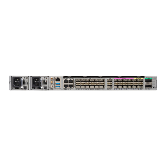
Activate an AC Power Supply Module
To install the AC power cables in the power supply slots:
1. Plug the power supply cord in the power supply module.
2. Insert the power supply cord into the tie [1, 3] and tighten the tie around the power supply cord as shown
in [2, 4] in the figure below.
Figure 14: Attach the AC Power Tie-and-Clip Cord
Note
These images are for only representation purposes. Certain variants of Cisco NCS 540 do not include a tie
for the power supply cord.
Activate an AC Power Supply Module
Perform the following procedure to activate an AC power supply:
Step 1
Plug the power cord into the power supply.
Step 2
Connect the other end of the power cord to an AC-input power source.
Step 3
Verify power supply operation by checking if the respective power supply front panel LED (PS0 or PS1) is green.
Step 4
If the LEDs indicate a power problem, see Troubleshooting for troubleshooting information.
Step 5
If you are also connecting a redundant AC power supply, repeat these steps for the second power source.
Note
If you are connecting a redundant AC power supply, ensure that each power supply is connected to a separate
power source in order to prevent power loss in the event of a power failure.
Install the Device
10
Install the Device