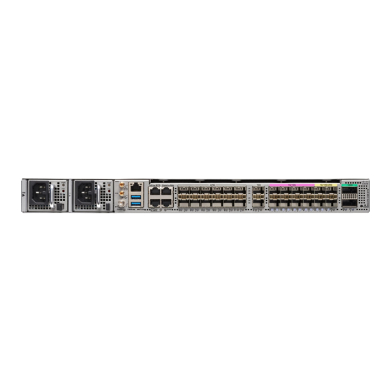
Cisco N540-FH-CSR-SYS Instrukcja instalacji - Strona 16
Przeglądaj online lub pobierz pdf Instrukcja instalacji dla Router sieciowy Cisco N540-FH-CSR-SYS. Cisco N540-FH-CSR-SYS 43 stron.
Również dla Cisco N540-FH-CSR-SYS: Przygotowanie do instalacji (14 strony)

Connecting Cables to a GPS Interface
Connecting Cables to a GPS Interface
Note
When installing the cables to the RSP, we recommend that you leave a service loop of extra cable to enable
fan tray removal.
The following sections describe how to connect cables from the router to a GPS unit for input or output timing
of frequency:
Connecting a Cable to the Input 10-MHz or 1-PPS Interface
Step 1
Connect one end of a mini-coax cable to the GPS unit.
Step 2
Connect the other end of the mini-coax cable to the 10-MHz or 1-PPS port on the RSP of the router.
Connecting a Cable to the Output 10MHz or 1PPS Interface
Step 1
Connect one end of a mini-coax cable to the Slave unit.
Step 2
Connect the other end of the mini-coax cable to the 10MHz or 1PPS port of the router.
Connecting a Cable to the GNSS Antenna Interface
1. Connect one end of a shielded coaxial cable to the GNSS RF IN port.
2. Connect the other end of the shielded coaxial cable to the GNSS antenna after the primary protector.
Note
The GNSS RF In port should have a primary protector installed to meet the Local Safety guidelines.
The GNSS RF In coaxial cable shield must be connected to the Facility Equipment Ground through the
chassis. The chassis must have the ground wire connected to the Facility Equipment Ground.
Install the Device
16
Install the Device
