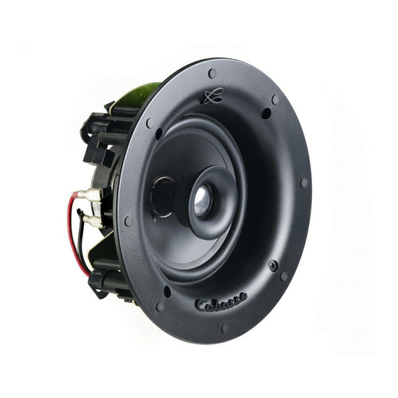
CABASSE ARCHIPEL 13ICP Instrukcja obsługi - Strona 11
Przeglądaj online lub pobierz pdf Instrukcja obsługi dla Głośniki CABASSE ARCHIPEL 13ICP. CABASSE ARCHIPEL 13ICP 17 stron. Loudspeakers
Również dla CABASSE ARCHIPEL 13ICP: Instrukcja obsługi (6 strony)

UNPACKING
After opening the top carton flaps, fold the carton flaps right
back and invert the carton contents. Remove the cutting tem-
plate and the upper foam form, then the grills followed by the
speakers. Keep the grilles away from the work area until you
are ready to fit them. We suggest you to retain the packing for
future use.
Check the contents:
2 speakers
2 grilles
2 PIN connectors
1 alignment template
1 manual
1 warranty card
SET-UP AND POSITIONING
Check the available depth at each speaker location. Add
the diameter of the speaker cable to the 222 mm (8.74 in)
depth of the Archipel enclosure measured from the surface
of the ceiling/panel.
Check that there is no conflict with other installations (pipe
work, air conditioning, power cabling etc.). In existing
construction, use a stud-finding tool to map the construction
accurately and a pipe detector to scan the proposed installation
position. Avoid installing the speakers on flimsy ducting,
which may be induced to rattle. Placement near a wall/ceiling
junction or in a corner is to be avoided as it may give rise to too
much bass and a boomy quality to the sound. If possible, keep
the speakers more than 0.5 m (20 in) from the ceiling edges.
Pour un résultat optimal dans le cas d'une construction
nouvelle et le montage dans des parois en plaques de plâtre
ou équivalent, nous conseillons d'utiliser le kit d'installation
Archipel 17 avec cadre et languettes de fixation.
Set-up
Check that the available depth and volume behind the panel
fit for the enclosure.
Position the template on the surface as required. Mark
around the outside of the template
ture neatly
.
2f
Connect the speaker cable to the terminals
amplifier. Respect the phase.
Position the speaker in the wall or ceiling and screw in the
4 screws visible from the front of the frame
swing out clamping dogs that locate behind the drywall.
Ensure that they have located properly and tighten the
screws. A certain amount of flexing of the frame is allowed
to take up unevenness in the mounting surface, but do not
over tighten the screws as excessive distortion of the frame
may occur.
If necessary, swivels the tweeter towards the listening area
with a gentle pressure on it's perimeter.Do no touch the dome
diaphragm of the tweeter. The rotation is possible in every
direction within an
angle up to 20°.
2
and cut the aper-
2d 2e
and to the
2a
. These screws
2k 2l
Position the grille of your choice in front of the speaker. It will
automatically be fitted thanks to the magnetic link.
Customising
The grille has a paintable white semi-matte finish, ready if
necessary to be re-finished to match your own decor.
ATTENTION: TURN OFF ALL THE AMPLIFIERS BEFORE
INTERCONNECTING THEM TO THE LOUDSPEAKERS. IN
ORDER TO CONNECT LOUDSPEAKERS PROPERLY, IT IS
MOST IMPORTANT TO KEEP IN MIND THE FOLLOWING
TWO FACTORS: CABLE SECTION AND PHASE.
CONNECTION
Cable section
To get the full sonic potential of Cabasse loudspeakers and
avoid over 15% power losses, the cables connecting the spea-
kers to the power amplifier must have the lowest possible
electrical resistance. Follow the here-under diagrams to select
the minimum correct cable gauge for your high impedance
installation.
Cable length/section for 8 ohms setting
(One speaker per amplifier output)
Max amp-speaker Distance
4.5 m
6 m
7.5 m
9 m
12 m
Maximum LS cable length for 100 V mode
Length (m)
30
20
0.75mm²
50
0.75mm²
100
0.75mm²
200
0.75mm²
400
0.75mm²
600
1mm²
800
1mm²
1000
1.5mm²
Maximum LS cable length for 70 V mode
Length (m)
30
20
0.75mm²
50
0.75mm²
100
0.75mm²
200
0.75mm²
400
1mm²
600
1.5mm²
800
1.5mm²
1000
2mm²
Phase
Amplifier and speaker manufacturers typically indicate
connection polarity in one of two ways: red and black or plus
and minus. In either case, always connect red or plus to red
or plus and black or minus to black or minus. Connections
should be identical for all channels.
Cable Section
1.5 mm
2
2 mm
2
2.5 mm
2
3 mm
2
4 mm
2
Power (W)
60
120
240
0.75mm²
0.75mm²
0.75mm²
0.75mm²
0.75mm²
0.75mm²
0,75mm²
0.75mm²
1mm²
0.75mm²
1mm²
1.5mm²
1mm²
1.5mm²
2mm²
1.5mm²
2mm²
2.5mm²
1.5mm²
2mm²
3mm²
2mm²
2.5mm²
4mm²
Power (W)
60
120
240
0.75mm²
0.75mm²
0.75mm²
0.75mm²
0.75mm²
1mm²
0.75mm²
1mm²
1.5mm²
1mm²
1.5mm²
2mm²
1.5mm²
2mm²
3mm²
2mm²
2.5mm²
4mm²
2mm²
3mm²
4mm²
2.5mm²
4mm²
6mm²
