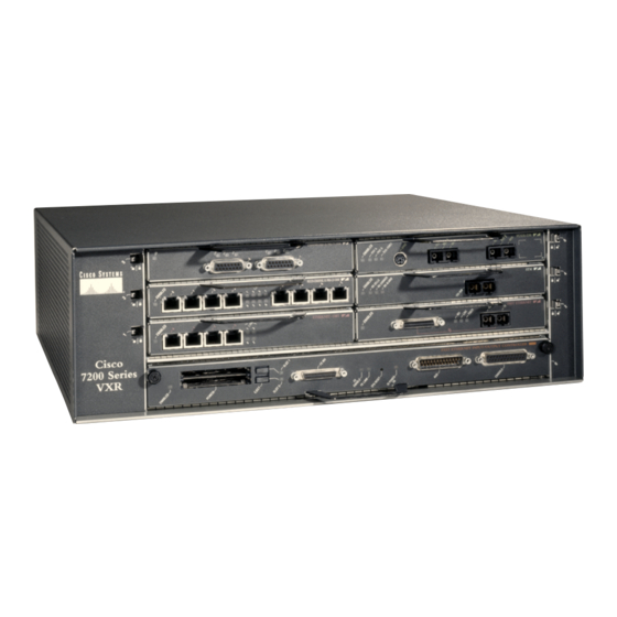
Cisco 7200 VXR Series Skrócona instrukcja obsługi - Strona 44
Przeglądaj online lub pobierz pdf Skrócona instrukcja obsługi dla Bezprzewodowy punkt dostępowy Cisco 7200 VXR Series. Cisco 7200 VXR Series 48 stron. Preparing for installation
Również dla Cisco 7200 VXR Series: Arkusz danych (12 strony), Podręcznik (14 strony)

Replace the Power Supply
Figure 27
Replacing the Power Supply
2
4
1
1
Power switch
2
PWR OK LED
3
AC/DC power input connection
Caution
Do not mix power supplies in Cisco 7200 VXR routers. In dual power supply configurations, both power supplies
must be of the same type (two AC-input power supplies or two DC-input power supplies).
Caution
To ensure adequate airflow across the router power supplies, a power supply or a power supply filler plate must be
installed in each power supply bay. Figure 18 shows a Cisco 7206VXR with an installed power supply filler plate.
Caution
The DC return connection to this system is to remain isolated from the system frame and chassis (DC-I).
Step 1
Power down the router.
Step 2
Disconnect the router from the power source (3).
Step 3
Unscrew the captive installation screws (4).
Step 4
Grasp the handle (5) and pull the power supply out of the chassis.
Step 5
Insert a new power supply of the same type that you removed and tighten the captive installation screws.
Step 6
Connect the power supply to the power source and power up the router.
Note
When powering off the router, wait 30 seconds before powering it on again.
3
5
2
4
1
4
Captive installation screws
5
Handle
3
5
44
