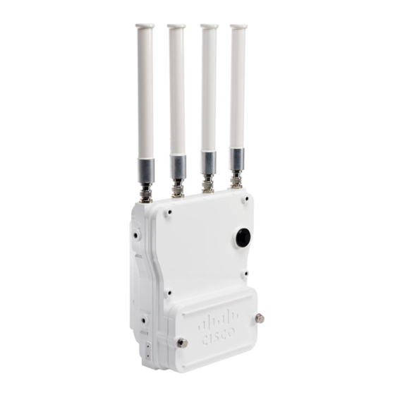
Cisco Catalyst IW6300H-AC Instrukcja instalacji - Strona 19
Przeglądaj online lub pobierz pdf Instrukcja instalacji dla Bezprzewodowy punkt dostępowy Cisco Catalyst IW6300H-AC. Cisco Catalyst IW6300H-AC 28 stron.

Installing the Access Point
Non-Cisco Antennas
Cisco does not support any third-party antennas. RF connectivity and compliance of third party antennas is
the user's responsibility. Cisco does not recommend any third-party antennas, and Cisco Technical Assistance
Center will not be able to provide any support for third-party antennas. Cisco's FCC Part 15 compliance is
only guaranteed with Cisco antennas or antennas that are of the same design and gain as Cisco antennas.
Grounding the Access Point
The access point must be grounded before connecting power.
In all outdoor installations you must follow these instructions to properly ground the case:
Procedure
Step 1
If using insulated 6-AWG copper ground wire, strip the insulation as required for the grounding lug.
Step 2
Use the appropriate crimping tool to crimp the bare 6-AWG copper ground wire to the supplied grounding
lug.
Note
Step 3
Open the anti-corrosion sealant (supplied), and apply a liberal amount over the metal surface, called the Ground
Pad, where the ground strap screw holes are located (see the following figure).
Figure 14: Position of the Ground Pad on the Right Side of the AP
1
Step 4
Connect the grounding lug to the access point grounding screw holes using the supplied two Phillips head
screws (M4 x10 mm) with lock washers. Tighten the grounding screw to 22 to 24 lb-in (2.49 to 2.71 Nm).
The grounding lug and hardware used must comply with local and national electrical codes.
Ground pad, where the ground strap screw holes are located.
Non-Cisco Antennas
Installing the Access Point
19
