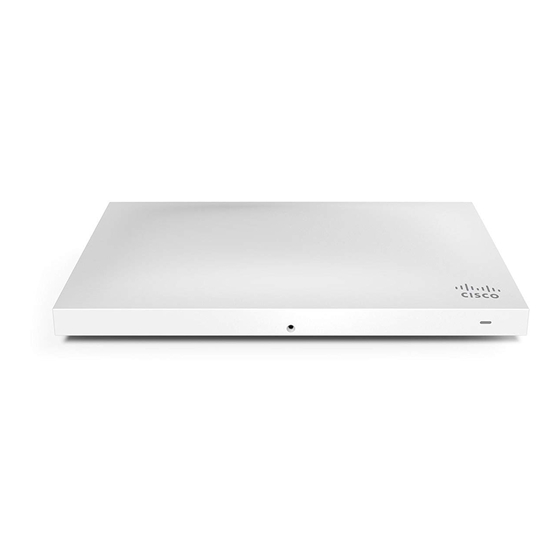
Cisco MERAKI MR34 Instrukcja instalacji - Strona 10
Przeglądaj online lub pobierz pdf Instrukcja instalacji dla Bezprzewodowy punkt dostępowy Cisco MERAKI MR34. Cisco MERAKI MR34 15 stron.

4. Attach the mount cradle to the T-rail clips using the mount cradle holes (marked with a "T").
Tip: Pre-assemble rubber spacers and screws to the mount cradle. The mount cradle can then be held with one hand
while the other hand holds a screwdriver. If mounting your MR34 to a dropped ceiling, skip to the
"Power the
MR34"
section.
Electrical Junction Box Mount Using mount cradle
The MR34 can be mounted to a 4" square cable junction box, a 3.5 or 4" round cable junction box, or various U.S. and
European outlet boxes (mounting screws are not included).
Using appropriate mounting hardware for your specific type of junction box, attach the mount cradle to the junction box.
Power the MR34
If mounting to an electrical junction box, feed the Ethernet cable through the cable access hole in the mount cradle. If
mounting to a wall or ceiling, the Ethernet cable will feed from behind the MR34.
Powering the MR34 with the Meraki AC Adapter (sold separately)
1. Plug the power cord into the MR34 and the other end into a wall outlet.
2. Plug an Ethernet cable that is connected to an active Ethernet connection into the Eth0 port on the MR34.
Powering the MR34 with the Meraki 802.3at Power over Ethernet Injector (sold separately)
1. Plug the power cord into the PoE Injector and the other end into wall power.
2. Plug an Ethernet cable that is connected to an active Ethernet connection into the "IN" port on the injector.
3. Route Ethernet cable from the "OUT" port on the injector to the Eth0 port in the cable bay of the MR34.
10
