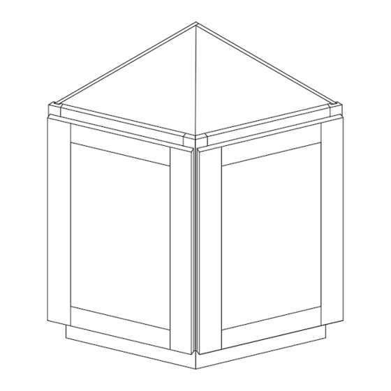
CABINETS TO GO Findley & Myers AB124 Instrukcja montażu - Strona 3
Przeglądaj online lub pobierz pdf Instrukcja montażu dla Wyposażenie wnętrz CABINETS TO GO Findley & Myers AB124. CABINETS TO GO Findley & Myers AB124 4 stron. Angle base cabinets
Również dla CABINETS TO GO Findley & Myers AB124: Instrukcja montażu (7 strony)

►Instructions:
1.
Place Back Panel (D) face down on a flat soft working surface (Figure 1).
2.
Insert side panel (B) into the grooves of back panel (D).(Figure 2) Align
the plastic half part of the cam lock connectors. Make sure it fits and lock connectors with a
screwdriver by turning the screw located on the cam lock connector to the right 180° (Figure 3)
3.
Insert the bottom panel (C) and shelf (E) (Figure 4), well align the cam locks and lock the connectors with a
screwdriver by turning the screw located on the cam lock connector to the right 180° (Figure 3).
4.
Assembling the Face Frames: Remove Door. Place one face frame (A) on a flat surface and install wood blocks (h) with screws (e) being careful of the placement .
e
h
Optional
1/16"
Qty 6
Qty 2
5.
Align the Frames with the side and back panel.(Figure 6&7) Align the cam locks and lock them by turning the screw to the right 180° (Figure 3)
B
f
4
Qty
Figure 6
6.
Connect both Toe Kicks (F) together with "L" brackets (g) with screws (c)(Figure 10A). Align the toe kicks with the cam locks at the bottom of the side and back panel.
(Figure 9) Install the Toe Kicks (F) by locking the cam locks at both ends. (Figure 10B) Install the plastic corner bracket (b) with screws (d) (Figure 11&12).
Install the remaining wooden block (h) with screws (e) as a shelf support onto the frames. (Figure 11)
g
c
2
4
Qty
Qty
(Note:There are no pre-drilled pilot holes in the frames. You can use a 1/16" drill bit, drilling 1/4" deep, if needed.)
e
Figure 5
h
Attach frames to bottom panel using screws (f) insuring frame is flush with the bottom panel, and aligned with each other.
A
(Figure 8) Finish attaching the frames to each other with the wooden blocks (h) that were attached in Step 4.
A
Figure 7
c
A
A
B
Figure 9
D
Figure 1
Figure 2
E
C
Figure 4
B
b
1
Q ty
g
h
B
Figure 10
Qty 4
Qty 1
Figure 11
Page 3
Figure 3
Figure 8
f
Install bumpers (a) on inside of doors.
d
Q
t
y
2
Top View
e
D
f
a
4
Qty
b
d
Figure 12
