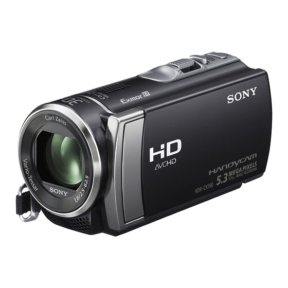
Sony CX200 Instrukcja serwisowa - Strona 16
Przeglądaj online lub pobierz pdf Instrukcja serwisowa dla Kamera Sony CX200. Sony CX200 27 stron.

Ver. 1.2 2012.05
The changed portions from
Ver. 1.1 are shown in blue.
2-1. EXPLODED VIEWS
2-1-1. OVERALL SECTION-1
(Projector Model)
Refer to page 2-4 about Non Projector Model
1
5
1
(Claws)
3
4
#2
3
#2
5
2
1
#2
Refer to page 2-4 about Non Projector Model
Ref. No.
Part No.
Description
1
4-412-130-01
ORNAMENT (2781), COVER (R)
2
A-1855-267-A
PANEL ASSY
(2781B), F (BLACK)
2
A-1861-022-A
PANEL ASSY
(2781S), F (SILVER)
3
4-412-135-01
BELT, FRONT
4
4-412-131-01
LID, MS
HDR-CX190/CX190E/CX200/CX200E/CX210/CX210E/PJ200/PJ200E/PJ210_L2
2
6
#2
2
(Claw)
2
#12
#2
Overall Section-2
(Projector Model)
124
(See Page 2-5)
Ref. No.
Part No.
Description
5
4-412-136-01
CABINET, USB
6
A-1857-765-A
CABINET ASSY (2781B), TOP (BLACK)
6
A-1861-018-A
CABINET ASSY (2781S), TOP (SILVER)
7
4-412-129-01
COVER (R (2781)), HINGE (BLACK)
7
4-412-129-11
COVER (R (2781)), HINGE (SILVER)
#2
2-635-562-31
SCREW (M1.7)
#12
3-080-204-21
SCREW, TAPPING, P2
DISASSEMBLY
1. Remove to numerical order (
Open the LCD (1) → #12 X 2
1
Right View
1
1
Open the LCD (4) → #2 X 2
4
Back View #2
4
Screw
#2: M1.7 X 4.0
#12: M1.7 X 5.0 (Tapping)
(Black)
2-635-562-31
#2
4
7
1.7
4.0
2-3
1
to
5
) in the left figure.
Rotate the LCD (2) → #2 X 4
2
Right View
#2
2
#12
#2 X 3
5
Top View
#2
(Black)
3-080-204-21
1.7
5.0
Left View
#2
Bottom View
#2
