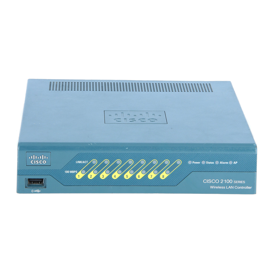
Cisco 5500 Series Podręcznik - Strona 12
Przeglądaj online lub pobierz pdf Podręcznik dla Sprzęt sieciowy Cisco 5500 Series. Cisco 5500 Series 19 stron. Cisco 8500 series
wireless lan controller
Również dla Cisco 5500 Series: Podręcznik konfiguracji (40 strony), Instrukcja instalacji (34 strony), Podręcznik konfiguracji (50 strony)

Replacing Hardware Components
Turn the power switch to the OFF (0) position on the power supply you are removing (see
Step 2
Remove the two screws securing the terminal block cover and slide the cover straight off the terminal
Step 3
block (see
Figure 7-9
Terminal
block
cover
Remove
Power
switch
Disconnect the DC-input wires from the terminal block. Disconnect the ground wire last.
Step 4
Disconnect the central office (CO) ground from the CO ground connector
Step 5
Figure 7-10 DC-Input Power Supply CO Ground
CO ground
connector
location
Loosen and remove the captive screws on the power supply (see
Step 6
Use both hands to remove and install power supplies.
Caution
Grasp the power supply handle with one hand and place your other hand underneath as you slowly pull
Step 7
the power supply out of the bay (see
Cisco MGC Software Release 7 Operations, Maintenance, and Troubleshooting Guide
7-12
Figure
7-9).
DC-Input Power Supply Front Panels
Remove
DC
FAN OUTPUT
OK
OK
FAIL
Captive screw
o
Chapter 7
Maintaining the Cisco Catalyst 5500 Multiswitch Router
o
Figure
7-11).
Figure
(Figure
7-10).
Figure
7-9).
7-9).
OL-0542-06
