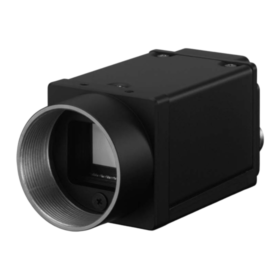
Sony XCG-CG160 Podręcznik - Strona 6
Przeglądaj online lub pobierz pdf Podręcznik dla Aparat cyfrowy Sony XCG-CG160. Sony XCG-CG160 9 stron. Digital video camera
Również dla Sony XCG-CG160: Podręcznik (9 strony)

Trigger Signal Input
Trigger signals can be input via the 2nd, 3rd, 4th pins of the DC IN
connector, or the software command. Switchover of the trigger
signal can be changed via the TriggerSource register.
Register
Parameter
Line1 (0)
Line2 (1)
Trigger
Line3 (2)
Source
Software (4)
FreeSetSequence (13)
PTP (15)
* XCG-CG160/CG160C: Unavailable. Dedicated to output.
Trigger signal polarity
Positive refers to a trigger signal polarity activated while rising from
Low to Hi, or during the Hi interval.
Negative refers to a trigger signal polarity activated while falling
from Hi to Low, or during the Low interval.
Register
Parameter
FallingEdge (0)
Trigger Activation
RisingEdge (1)
DC IN connector specifications
2.0 µs or less
2.0 µs or less
10 µs to 2 s
1 frame time or more
Trigger input polarity = Negative
2.0 µs or less
2.0 µs or less
10 µs to 2 s
1 frame time or more
Trigger input polarity = Positive
Note
• When inputting a trigger signal to the camera using the DC-
700/CE, use DC 5 V or less at the logical high level.
• Make sure to supply power to the camera module and confirm
that the camera module is operating before inputting a trigger
signal. If you input trigger signal to a camera module without
the power supplied, this may cause a malfunction of the
camera module.
Trigger Signal Specifications
Trigger input polarity = Positive
2.0 µs
2.0 µs or less
or less
10 μs to 2 s
Trigger input polarity = Negative
10 µs to 2 s
2.0 µs
or less
Voltage reading shows figure by terminal with 10 kΩ or more.
Note
When inputting a trigger signal to the camera using the DC-700/DC-
700CE, use DC 5 V or less at the logical high level.
XCG-CG510/CG510C/CG240/CG240C/CG160/CG160C/CG40
Setting
DC IN connector 2nd pin (GPI1)
DC IN connector 3rd pin (GPI2)
DC IN connector 4th pin (GPI3) *
Software (TriggerSoftware register)
FreeSetSequence mode
IEEE1588 synchronization mode
Setting
Negative
Positive
5 to 24 V (DC IN
connector 2nd pin)
3.5 to 5.5 V (DC IN
connector 3rd and
4th pins*)
0 to 0.4 V
5 to 24 V (DC IN
connector 2nd pin)
3.5 to 5.5 V (DC IN
connector 3rd and
4th pins*)
0 to 0.4 V
* Except XCG-CG160/CG160C
5 V to 24 V
0 V to +0.4 V
2.0 µs or less
5 V to 24 V
0 V to 0.4 V
Trigger Modes
There are five modes, Free run, Bulk Trigger, Sequential Trigger,
Burst Trigger and Freeset squence.
Free Run
The camera operates without a trigger signal and performs the
video output operation continuously after the shutter (exposure) is
finished when operating in Free run mode.
• Trigger edge detection (Polarity: positive)
Trigger signal
Exposure
• Trigger width detection (Polarity: positive)
a
Trigger signal
a
Exposure
Bulk Trigger (except XCG-CG40)
Different camera setting configurations are stored in memory
channels beforehand, with the different settings applied to acquire
multiple video images at each trigger event. In the following
diagram, two images are acquired in one cycle.
Trigger signal
Exposure
Memory channel
1 settings
Sequential Trigger (except XCG-CG40)
Different camera setting configurations are stored in memory
channels beforehand, with the different settings applied in
sequence to acquire a different image with each trigger event. In
the following diagram, two images with different exposure settings
are acquired in one cycle.
Trigger signal
Exposure
Memory channel
1 settings
Burst Trigger
This is a feature capable of continuous shooting at the trigger
timing and specifying the number of exposures, exposure interval,
and exposure time. Select from the mode that repeats one
exposure time or the mode that switches between 2 exposure
times repeatedly. Furthermore, there is another mode that repeats
only while the trigger signal is on.
(A) When 1 pattern of exposure time is set
Set the number of exposures, exposure interval (1), and exposure
time (2) Continuous shooting at the trigger timing
Trigger signal
Exposure
2
Camera output
(B) When 2 patterns of exposure times are set
Set the number of exposures, exposure interval (1), and exposure
time (2) Continuous shooting at the trigger timing
Trigger signal
-1
2
2
Exposure
Camera output
b
b
Memory channel
2 settings
Memory channel
2 settings
1
1
-2
