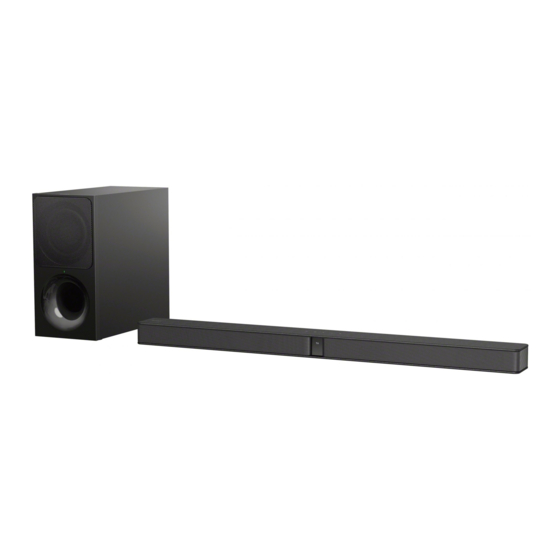
Sony SA-WCT291 Instrukcja serwisowa - Strona 11
Przeglądaj online lub pobierz pdf Instrukcja serwisowa dla System stereo Sony SA-WCT291. Sony SA-WCT291 42 stron. Sound bar and active speaker system
Również dla Sony SA-WCT291: Instrukcja serwisowa (24 strony)

2-5.
BLUETOOTH MODULE, MAIN BOARD
Note 1: When the complete MAIN board is replaced, refer to
"NOTES ON THE WIRELESS CONNECTION (LINK)
AFTER REPAIRS ARE COMPLETE" on page 5.
7 Remove the wire from
stopper, wiring.
stopper,
wiring
SWITCHING
REGULATOR
Note: The wire must not touch
the inductor.
2-6.
SWITCHING REGULATOR
1 two screws
(+BVTP 3
• Abbreviation
CND : Canadian model
E12
: 220-240 V AC area in E model
9 six screws
(+BVTP 3
8)
MAIN board
8 CN1000 (10P)
inductors
8)
4
Note 2: When the BLUETOOTH module is replaced, refer to
"NOTES ON THE WIRELESS CONNECTION (LINK)
AFTER REPAIRS ARE COMPLETE" on page 5.
qa MAIN board
wire (flat type) (18 core)
1
(CN2002)
0 one screw
(+B 3
wire (flat type) (7 core)
6
(CN3000)
1 three screws
(+BVTP 3
8)
2 stopper, wiring
3 SWITCHING REGULATOR
3L411W (EXCEPT US, CND, E12)
3L411W-1 (E12)
3L411L (US, CND)
6 two screws
5 insulator
(+BVTP 3
(CG-BAR)
7 USB board
HT-CT290/CT291
2 one screw
(+BVTP 3
8)
3 BLUETOOTH module
4 one screw
(+BVTP 3
8)
5 holder, BT (CG-BAR)
5)
8)
11
