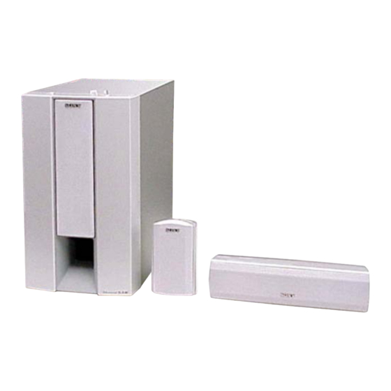
Sony SA-WMS345 Instrukcja serwisowa - Strona 7
Przeglądaj online lub pobierz pdf Instrukcja serwisowa dla System stereo Sony SA-WMS345. Sony SA-WMS345 16 stron. Micro satellite system
Również dla Sony SA-WMS345: Instrukcja serwisowa (16 strony)

NOTE:
• The mechanical parts with no reference
number in the exploded views are not supplied.
• Items marked "*" are not stocked since
they are seldom required for routine service.
Some delay should be anticipated
when ordering these items.
• Abbreviation
CND : Canadian model
AUS : Australian model
SP
: Singapore model
MY : Malaysia model
2-1. FRONT PANEL SECTION
(SA-WMS345)
SP1
#1
#1
5
4
2
not
supplied
Ref. No.
Part No.
Description
1
1-680-785-11 CONTROL BOARD
2
X-4955-364-1 PANEL ASSY, FRONT (US,CND)
2
X-4955-488-1 PANEL ASSY, FRONT (EXCEPT US,CND)
3
3-703-564-21 SCREW, TAPPING
4
4-227-298-01 SHEET
5
4-999-482-11 KNOB (VOL) (SP,MY)
5
4-999-482-51 KNOB (VOL) (EXCEPT SP,MY)
6
4-231-866-01 PACKING
SECTION 2
EXPLODED VIEWS
• Color Indication of Appearance Parts
Example :
KNOB, BALANCE (WHITE) ... (RED)
Parts Color Cabinet's Color
• Accessories are given in the last of this
parts list.
supplied with
RV201 and S201
8
7
3
#2
#2
3
1
Remark
Ref. No.
7
8
8
9
SP1
#1
#2
SA-VE345/WMS345/SS-CN345/V345
The components identified by
mark 0 or dotted line with mark
0 are critical for safety.
R
R
Replace only with part number
specified.
Les composants identifiés par une
marque 0 sont critiques pour
la sécurité.
Ne les remplacer que par une piéce
portant le numéro spécifié.
6
9
Part No.
Description
1-680-788-11 LED BOARD
4-973-938-31 KNOB (A), PUSH (SP,MY)
4-973-938-61 KNOB (A), PUSH (EXCEPT SP,MY)
1-680-787-11 POWER SWITCH BOARD
1-529-296-12 SPEAKER (20cm) (WOOFER)
7-685-664-79 SCREW +P 4X20 TYPE1
7-685-646-79 SCREW +BVTP 3X8 TYPE2 N-S
Ver 1.1
Remark
7
