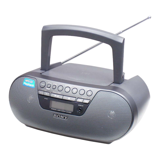
Sony ZS-S10CP Instrukcja serwisowa - Strona 15
Przeglądaj online lub pobierz pdf Instrukcja serwisowa dla System stereo Sony ZS-S10CP. Sony ZS-S10CP 40 stron. Personal audio system
Również dla Sony ZS-S10CP: Instrukcja obsługi (2 strony), Instrukcja obsługi (2 strony), Instrukcja uruchamiania (2 strony)

EEPROM CLR
It can clear the EEPROM.
Procedure:
1. While pressing two buttons of [DISPLAY] and [
neously and connect the AC power cord.
2. The EEPROM is cleared, and the message "CLr" is displayed
on the liquid crystal display, then becomes the standby state.
PANEL AND KEY TEST
It can check the liquid crystal display and button.
Procedure:
1. While pressing two buttons of [x] and [DISPLAY] simultane-
ously and connect the AC power cord.
2. It enters the panel and key test mode, and all segments on the
liquid crystal display light up.
3. Each time a button is pressed, the segments on the liquid crys-
tal display corresponding to each button disappear.
4. When all buttons are pressed, all segments on the liquid crystal
display disappear.
5. When the [DISPLAY] button is pressed, becomes the standby
state.
Releasing method:
Disconnect the AC power cord.
CD TEST MODE
It can check the focus error and tracking error.
Procedure:
1. Connect the oscilloscope to TP895 (FEI) and TP814 (GND) on
the MAIN board.
oscilloscope
MAIN board
TP895 (FEI)
+
TP814 (GND)
–
2. Open the CD lid.
3. While pressing [x] button for around 8 seconds and connect
the AC power cord.
4. It enters the CD test mode, and the message "tEST 1" is dis-
played on the liquid crystal display.
5. When the message "TEST 1" is displayed on the liquid crystal
display, press the [
] button.
u
6. It enters the focus error test mode, and the message "FE" is
displayed on the liquid crystal display.
7. When the CD disc is placed and CD lid is closed, focus error
starts.
8. Confi rm that oscilloscope waveform is as shown in the fi gure
below.
VOLT/DIV: 200 mV
TIME/DIV: 2 ms
1.2 ± 0.6 Vp-p
9. Disconnect the AC power cord to release the focus error test
mode.
ZS-S10CP
SECTION 3
TEST MODE
10. Connect the oscilloscope to TP805 (TEI) and TP814 (GND) on
the MAIN board.
oscilloscope
MAIN board
] simulta-
>
TP805 (TEI)
TP814 (GND)
11. Open the CD lid.
12. While pressing [x] button for around 8 seconds and connect
the AC power cord.
13. It enters the CD test mode, and the message "tEST 1" is dis-
played on the liquid crystal display.
14. When the [
] button is pressed, the message on the liquid
>
crystal display change to "tEST 2".
(When the [
] button is pressed again, the message on the
>
liquid crystal display change to "tEST 1")
15. It enters the tracking error test mode, and the message "TE" is
displayed on the liquid crystal display.
16. When the CD lid is closed, tracking error starts.
17. Confi rm that oscilloscope waveform is as shown in the fi gure
below.
Releasing method:
Press the [POWER] button or disconnect the AC power cord.
Connection Location:
– MAIN Board (Conductor Side) –
TP805
(TEI)
TUNER SECTION
[AM]
Setting:
Function: RADIO
+
Band: AM
–
AM RF signal
generator
30% amplitude
modulation by
400 Hz signal
Output level:
as low as possible
[FM]
Setting:
Function: RADIO
Band: FM
VOLT/DIV: 500 mV
TIME/DIV: 2 ms
FM RF signal
generator
1.2 ± 0.6 Vp-p
75 kHz frequency
deviation by
1 kHz signal
Output level:
as low as possible
Note: Perform FM frequency coverage check after removing FM tele-
scopic antenna (ANT1).
no mark: Australian, Chilean, Peruvian and Asian models
AM FREQUENCY COVERAGE CHECK
Check that reading on level meter is the maximum
Confi rmation
TP895
Confi rmation
(FEI)
FM FREQUENCY COVERAGE CHECK
Check that reading on level meter is the maximum
TP814
Confi rmation
(GND)
Confi rmation
15
15
SECTION 4
ELECTRICAL CHECKS
0 dB = 1 V
CD SECTION
Note:
1. CD block is basically constructed to operate without adjustment.
2. Use YEDS-18 disc (Part No. 3-702-101-01) unless otherwise indicat-
ed.
3. Use an oscilloscope with more than 10 M impedance.
4. Clean the object lens by an applicator with neutral detergent when the
Put the lead-wire
signal level is low than specifi ed value with the following checks.
antenna close to
5. Check the focus bias check when optical pick-up block is replaced.
level meter
the unit.
32
FOCUS BIAS CHECK
+
unit
HP JACK board
i
jack (J302)
Procedure:
1. Connect the oscilloscope to TP804 (RF) and TP711 (VREF)
on the MAIN board.
2. In the standby state, press the [POWER] button to turn the
power on.
3. Press the [CD] button to turn the CD function.
4. Set the disc (YEDS-18) and press the [
5. Confi rm that oscilloscope waveform is as shown in the fi gure
level meter
MAIN board
below. (eye pattern)
JW101
A good eye pattern means that the diamond shape () in the
32
0.01 F
center of the waveform can be clearly distinguished.
+
unit
HP JACK board
jack (J302)
i
MAIN board
TP814 (GND)
(
): Mexican and Panamanian models
Connection Location:
– MAIN Board (Conductor Side) –
531 (530) kHz
1,602 (1,710) kHz
JW101
87.5 MHz
108 MHz
ZS-S10CP
oscilloscope
MAIN board
TP804 (RF)
+
TP711 (VREF)
–
] button to playback.
u
VOLT/DIV: 200 mV
TIME/DIV: 500 ns
level: 1.5 Vp-p
TP804
TP711
(RF)
(VREF)
TP814
(GND)
