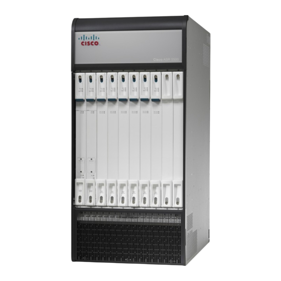
Cisco ASR 5500 Instrukcja instalacji - Strona 20
Przeglądaj online lub pobierz pdf Instrukcja instalacji dla Sprzęt sieciowy Cisco ASR 5500. Cisco ASR 5500 31 stron.
Również dla Cisco ASR 5500: Przegląd procedury instalacji (6 strony)

Taking Corrective Action
Taking Corrective Action
In the event that an issue was discovered with an installed application or line card, depending on the severity,
it may be necessary to take corrective action.
The system provides several redundancy and fail-over mechanisms to address issues with application and line
cards in order to minimize system downtime and data loss. These mechanisms are described in the sections
that follow.
Switching MIOs
When the system boots up, the MIO/UMIO/MIO2 installed in chassis slot 5 will boot into the Active mode
and begin booting other system components. The MIO/UMIO/MIO2 installed in chassis slot 6 will automatically
be booted into Standby mode dictating that it will serve as a redundant component. The active
MIO/UMIO/MIO2 automatically synchronizes currently running tasks or processes with the standby
MIO/UMIO/MIO2.
In the event of a critical failure on the MIO/UMIO/MIO2 in slot 5, system control will be automatically
switched to the standby MIO/UMIO/MIO2 in slot 6. This is a relatively seamless transition because the two
are synchronized. The formerly active MIO will then enter the standby mode allowing it to be safely replaced
or restored.
In the event that an issue arises that is not severe enough for the system to perform an automatic switchover,
a manual switchover can be invoked by executing the following commands from the Exec mode prompt.
Step 1
Initiate a manual MIO/UMIO/MIO2 switch over by entering the following command:
[local]host_name#
You will receive the following prompt:
Are You Sure? [Yes|No]:
Step 2
Press Y to start the switchover.
Step 3
Verify that the switchover was successful by entering the show card table command at the Exec mode prompt:
Check the entry in the Oper State column next to the MIO/UMIO/MIO2 just switched. Its state should be Standby.
Busying Out a DPC
This busy-out command moves processes from the source DPC/UDPC or DPC2/UDPC2 to the destination
DPC/UDPC or DPC2/UDPC2, or disables the DPC/UDPC or DPC2/UDPC2 from accepting any new calls.
When busy-out is enabled, the DPC/UDPC or DPC2/UDPC2 stops receiving new calls but continues to process
calls until they are completed. The command prompt is returned once the command is initiated. The busy-out
procedure is completed in background.
Step 1
Initiate a busy-out by entering the following command:
[local]host_name#
Troubleshooting
20
card switch from
<5 or 6>
card busy-out
slot_number
to
<6 or 5>
Troubleshooting
