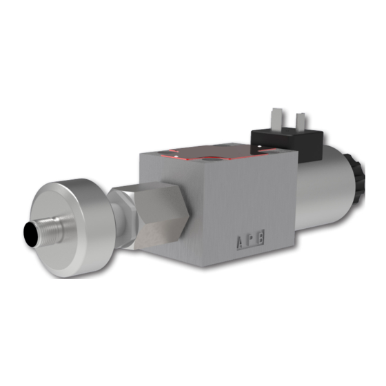
Argo-Hytos RPE3-062 S3 Series Instrukcja obsługi - Strona 11
Przeglądaj online lub pobierz pdf Instrukcja obsługi dla Jednostka sterująca Argo-Hytos RPE3-062 S3 Series. Argo-Hytos RPE3-062 S3 Series 16 stron. 4/2 hydraulic directional control valve with axial spool position sensor, solenoid operated, suitable for use as a safety component with certified functional safety

WARNING
The valve is designed for mounting on a connection plate that has the required flatness and surface roughness, is fitted with a DN 06 mounting
pattern according to ISO 4401 (ISO 4401-03-02-0-05), is undamaged and clean. The mounting position of the valve is arbitrary.
4xM5-6Hx13
31,75 (1.25)
T
25,9 (1.16)
31 (1.22)
Ports P,A, B, T - max. ∅7,5 mm (0.29 in)
Mounting for DN 06
ISO 4401--03-02-0-05
› Position the the directional control valve correctly. Correct position is aided by the port markings (P, A, B, T) on the product label.
The spacing of the bolt orrifices on the connection pattern are different to prevent installation of a mispositioned valve.
› Carefully fit the valve on the connection plate so that the ports in the valve and in the plate (P-P, A-A, B-B, T-T) are correctly connected.
Make sure that none of the sealing rings fall out of the recess in the body when fitting the valve.
› Insert the four mounting screws with cylindrical head and hexagon socket M5x45 DIN 912-10.9 into the holes in the valve body.
› Successively tighten the screws crosswise to a torque of 8.9 + 1 Nm using a size 4 inbus wrench.
WARNING
Dimensions of the RPE2-06x/xS3 directional control valve,
Valve with one solenoid „a"
Spool symbols
R11, Z51, R31...
Valve with one solenoid „b"
Spool symbols
X11, K11, Z11...
10 Nm (7.4 lbf.ft)
www.argo-hytos.com
Operating_Instructions_RPE3-062x/xS3_14087_1en_05/2022
Slippery valve surface
The valve contains a small amount of residual oil after a hydraulic function test carried out by the manufacturer.
If the surface of the unpacked valve is contaminated with oil, remove the oil using a cleaning cloth. A slippery
valve surface can cause the valve to fall during handling and cause minor injury or damage to the valve.
0,75 (0.03)
B
G
P
A
5,1 (0.20)
15,5 (0.61)
Correct installation of the valve
Failure to comply with connection plate requirements, dropped or damaged sealing rings, contaminating particles
in the dividing plane, incorrectly tightened screws lead to leakage of working fluid in the dividing plane.
Use original screws with defined length and increased material tensile strength.
±
±
Connection surface free of mechanical damage (indentations, etc.)
and dirt.
Requirements for flatness and surface roughness of the connection plate
in mm (in)
- (podle seřízení nuly)
Plastic nut
3+1 Nm
(2.2+0.7 lbf.ft)
6,3
Upevňovací šrouby
8,9+1 Nm (7+0.7 lbf.ft)
M5 x 45 DIN 912-10,9
Page 11
