Digitrax SE74 Podręcznik - Strona 6
Przeglądaj online lub pobierz pdf Podręcznik dla Konwerter mediów Digitrax SE74. Digitrax SE74 12 stron.

5.0 External hardware Input lines:
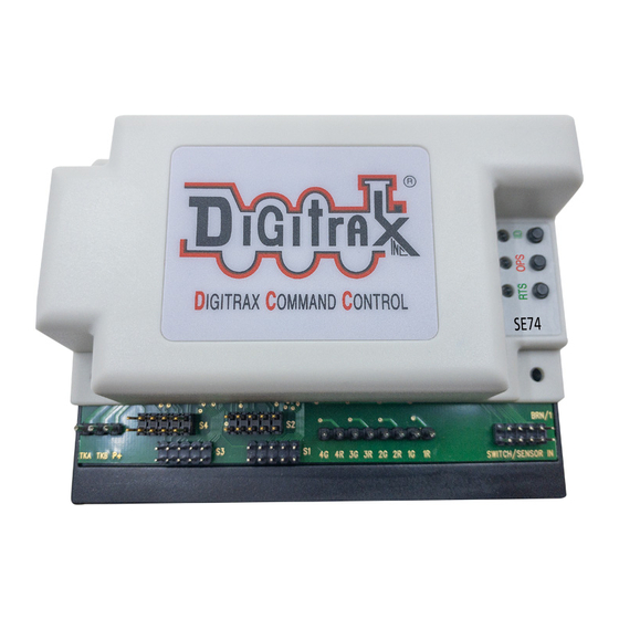
The SE74 has eight external hardware control lines on the "SWITCH/SENSOR
IN" 10-pin PCB header using a plug-in 10-pin ribbon cable. The 6" Factory
ribbon cable pin 1 edge should be on the right side when plugged in. With Gray
cable the red stripe is pin 1 edge, and for 10-color cable pin 1 is BROWN, with
wire colors shown in Table 2.
If you use these external lines, connect the wires from the pins of Table 2 to your
custom wiring by e.g. screw terminal blocks. If using a Gray non-color ribbon
cable, make sure pin 1 and counted pin numbers match Table 2 usage.
Alternately, plug in a DSXC4
board with its ribbon cable, which
will support up to 4 DSXCP1 fascia
SW controls with switch state
indicating LEDs.
A +5V Reference voltage is
provided on pin 10/ribbon cable
BLACK wire for setting an ON/ac-
tive level, and a 0V/OFF reference
level on pin 9 or the WHITE wire.
DO not draw more than 100mA
from the BLACK wire. The SW/
SENS wires on pins 1/BROWN
through 8/GRAY are rated for up
to +16V maximum input voltage,
but best practice is 0V to 5V opera-
tion.
1.
The SW1,SW2,SW3,and SW4 pins will toggle the state of the same number
output when briefly connected to the +5V ON voltage on the BLACK wire or
pin10. If the SE74 is connected to LocoNet this will occur as a SW# message
to make the change and notify the system it has occurred. Wire to momen-
tary press-on buttons for SW control.
2.
The pins SENS1,SENS2, SENS3 and SENS4 will send a LocoNet Block
Occupancy or DS message at the SW# of the output. This will be BLOCK
OCCUPIED when the line is above +4V and a BLOCK UNOCCUPIED when
between 0V/WHITE and +2V.
3.
For example; if the SENS2/YELLOW line of the input ribbon cable is con-
nected to the BLACK +5V Reference wire, the DS number reported will be
SW# used for Output 2R/2G. If SW10 is the SE74 BASE address of Output1,
then Output2 is SW11 and the DS message will be Block 11 OCCUPIED.
4.
A disconnected SENS line will report as UNOCCUPIED.
5.
The BD4N does not plug directly into a 10 pin header, and will not operate.
Connect the 5 wires used by the BD4N by name via a terminal strip. More
conveniently, you may connect the BD4N through a plugged in DSXC4 board
with ribbon cables for true plug and play connectivity. This will also allow
DSXCP1 SW control and state display.
6.
These ribbon cable wires should not connect to any other voltage levels or
loads other than those defined here.
© 2022 Digitrax, Inc.
Table 2: SE74 Input lines
Pin# Wire Color
1
BROWN
2
RED
3
ORANGE
4
YELLOW
5
GREEN
6
BLUE
7
VIOLET
8
GRAY
9
WHITE
10
BLACK
— 6 —
Function
SW1 Toggle, +momentary
SENS1 occupancy level
SW2 Toggle, +momentary
SENS2 occupancy level
SW3 Toggle, +momentary
SENS3 occupancy level
SW4 Toggle, +momentary
SENS4 occupancy level
0V reference
+5V reference
www.digitrax.com
