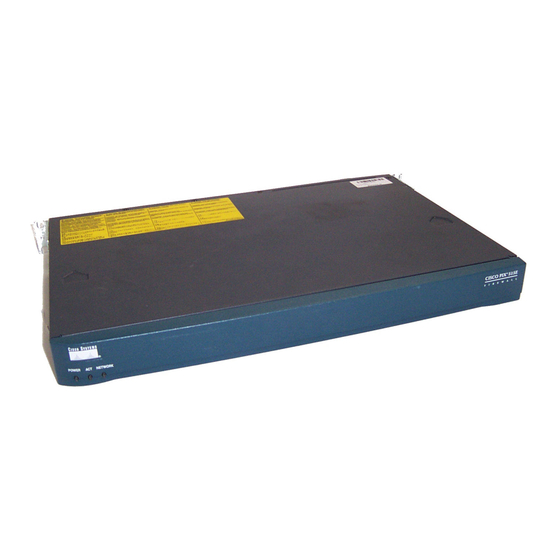
Cisco PIX-515E Skrócona instrukcja obsługi - Strona 4
Przeglądaj online lub pobierz pdf Skrócona instrukcja obsługi dla Sprzęt sieciowy Cisco PIX-515E. Cisco PIX-515E 42 stron. Security appliance
Również dla Cisco PIX-515E: Skrócona instrukcja obsługi (42 strony)

2
Installing the PIX 515E Security Appliance
This section describes how to install your PIX 515E security appliance into your own network, which
might resemble the model in Figure 1.
Figure 1
Sample Network Layout
DMZ server
Laptop
computer
Printer
To install the PIX 515E security appliance, complete these steps:
Mount the chassis in a rack by performing the following steps:
Step 1
a. Attach the brackets to the chassis with the supplied screws. The brackets attach to the holes
near the front of the chassis.
b. Attach the chassis to the equipment rack.
Use one of the provided yellow Ethernet cables (72-1482-01) to connect the outside 10/100
Step 2
Ethernet interface, Ethernet 0, to a DSL modem, cable modem, router, or switch.
Use the other provided yellow Ethernet cable (72-1482-01) to connect the inside 10/100
Step 3
Ethernet interface, Ethernet 1, to a switch or hub.
Connect one end of the power cable to the rear of the PIX 515E security appliance and the
Step 4
other end to a power outlet.
Power up the PIX 515E security appliance. The power switch is located at the rear of the
Step 5
chassis.
4
Switch
DMZ
Inside
Switch
Personal
computer
PIX 515E
Outside
Power
Router
Internet
cable
