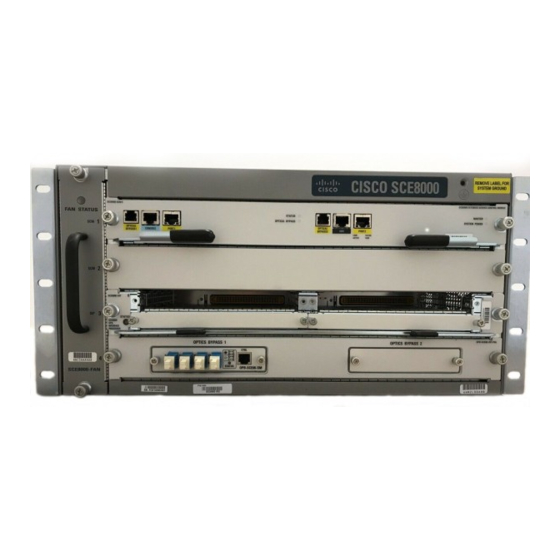
Cisco SCE8000 GBE Skrócona instrukcja obsługi - Strona 14
Przeglądaj online lub pobierz pdf Skrócona instrukcja obsługi dla Sprzęt sieciowy Cisco SCE8000 GBE. Cisco SCE8000 GBE 25 stron. 10gbe platform
Również dla Cisco SCE8000 GBE: Podręcznik konfiguracji (18 strony), Procedury demontażu i wymiany (36 strony), Instalacja (21 strony)

Figure 9
Cabling the Management Port
S C E 8 0 0 0
Connect the other end of the Ethernet cable into your management network. The Link LED on the SCE8000
Step 2
management port lights.
Test connectivity. From the host that you intend to use for remote management, ping to the Cisco SCE8000 by typing
Step 3
ping and the Cisco SCE8000 IP address, and pressing Enter.
This verifies that an active connection exists between the specified station and the management port.
5
Cabling Line Ports
This chapter describes cabling the Cisco SCE8000 10 Gigabit Ethernet ports for single, cascaded, and multigigabit service
control platforms (MGSCP) topologies.
The 10 Gigabit Ethernet ports are located on the 10 G SPA modules, which are installed in the SCE8000-SIP module in slot #3
of the Cisco SCE8000 chassis.
Warning
Class 1 laser. Avoid exposure to radiation and do not stare into open aperture.
SCE8000 Connectivity Summary
Table 3 through Table 7 summarize SCE 8000 connectivity for basic topologies. Receive-only topologies use only receive fibers.
You can implement receive-only topologies using either an optical splitter or a switch. If you use a switch, it must
Note
support SPAN functionality that includes separation between ingress and egress traffic and multiple SPAN-port
destinations.
Table 3
Single Link Connectivity
Port
Link
3/0/0
Link 0
3/1/0
Link 0
14
1
2
3
- S C M - E
O P T IC A
L
B Y P A S
S 1
C O N S O
L E
P O R T 1
1 0 /1 0 0 /
1 0 0 0
Side
Subscribers
Network
L IN K /
A C T IV E
