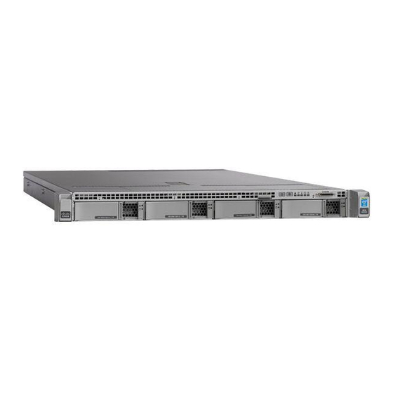
Cisco APIC L4 Instrukcja instalacji i obsługi - Strona 14
Przeglądaj online lub pobierz pdf Instrukcja instalacji i obsługi dla Serwer Cisco APIC L4. Cisco APIC L4 46 stron.

Serviceable Component Locations
Figure 5: Internal Diagnostic LED Locations
1
Fan module fault LEDs (one behind each fan
connector on the motherboard)
• Amber—Fan has a fault or is not fully seated.
• Green—Fan is OK.
2
CPU fault LEDs (one behind each CPU socket on
the motherboard).
These LEDs operate only when the server is in
standby power mode.
• Amber—CPU has a fault.
• Off—CPU is OK.
Serviceable Component Locations
This topic shows the locations of the field-replaceable components and service-related items. The view in the
following figure shows the server with the top cover removed.
Cisco APIC M4/L4 Server Installation and Service Guide
10
3
DIMM fault LEDs (one behind each DIMM socket
on the motherboard)
These LEDs operate only when the server is in
standby power mode.
• Amber—DIMM has a fault.
• Off—DIMM is OK.
-
Overview
