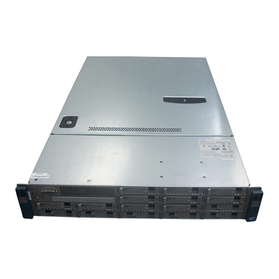
Cisco UCS C Series Instrukcja instalacji - Strona 12
Przeglądaj online lub pobierz pdf Instrukcja instalacji dla Serwer Cisco UCS C Series. Cisco UCS C Series 19 stron. Security manager 4.3
Również dla Cisco UCS C Series: Wskazówki dotyczące rozwiązywania problemów (11 strony), Instrukcja aktualizacji (11 strony), Instrukcja aktualizacji (10 strony), Skrócona instrukcja obsługi (12 strony), Konfiguracja (10 strony)

Connecting to the Server Remotely For Setup
• Connect an optional KVM cable (Cisco PID N20-BKVM) to the KVM connector on the front panel. Connect your
USB keyboard and VGA monitor to the KVM cable.
• Connect a USB keyboard and VGA monitor to the corresponding connectors on the rear panel.
Step 3
Open the Cisco IMC Configuration Utility:
a) Press and hold the front panel power button for four seconds to boot the server.
b) During bootup, press F8 when prompted to open the Cisco IMC Configuration Utility.
The first time that you enter the Cisco IMC Configuration Utility, you are prompted to change the default
Note
password. The default password is password. The Strong Password feature is enabled.
The following are the requirements for Strong Password:
• The password can have minimum 8 characters; maximum 14 characters.
• The password must not contain the user's name.
• The password must contain characters from three of the following four categories:
• English uppercase letters (A through Z)
• English lowercase letters (a through z)
• Base 10 digits (0 through 9)
• Non-alphabetic characters !, @, #, $, %, ^, &, *, -, _, =, "
Step 4
Continue with
Setting Up the System With the Cisco IMC Configuration Utility, on page
Connecting to the Server Remotely For Setup
This procedure requires the following equipment:
• One RJ-45 Ethernet cable that is connected to your management LAN.
Before you begin
Note
To configure the system remotely, you must have a DHCP server on the same network as the system. Your
DHCP server must be preconfigured with the range of MAC addresses for this server node. This server node
has a range of six MAC addresses assigned to the Cisco IMC. The MAC address printed on the label is the
beginning of the range of six contiguous MAC addresses.
Step 1
Attach a power cord to each power supply in your server, and then attach each power cord to a grounded AC power outlet.
Wait for approximately two minutes to let the server boot to standby power during the first bootup. You can verify system
power status by looking at the system Power Status LED on the front panel. The system is in standby power mode when
the LED is amber.
Installing the Server
12
Installing the Server
13.
