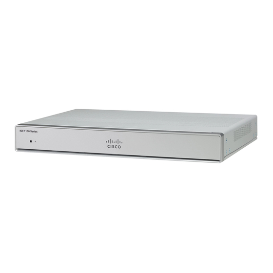
Cisco C1100TGX-1N24P32A Instrukcja instalacji sprzętu - Strona 7
Przeglądaj online lub pobierz pdf Instrukcja instalacji sprzętu dla Gateway Cisco C1100TGX-1N24P32A. Cisco C1100TGX-1N24P32A 44 stron. Terminal gateway

About Cisco 1100 Terminal Gateway Routers
Figure 3: C1100TG-1N32A - Rear View
1
3
5
Figure 4: C1100TG-1N24P32A and C1100TGX-1N24P32A - Rear View
1
3
5
LED Indicators
The following figures and table summarizes the LED indicators that are located on the chassis of the Cisco
1100 Terminal Gateway Routers.
USB 3.0
RJ-45 Console, AUX
Grounding Attachment
USB 3.0
RJ-45 Console, AUX
Grounding Attachment
2
6-pin Power Connector
4
ASYNC LED
6
Power Supply
2
6-pin Power Connector
4
ASYNC LED
6
Power Supply
Hardware Installation Guide for the Cisco 1100 Terminal Gateway
LED Indicators
3
