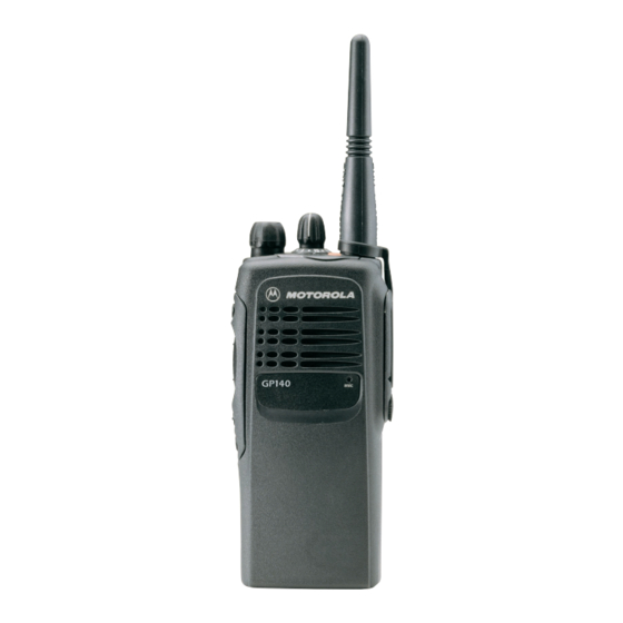
Motorola GP1280 Series Podstawowa instrukcja serwisowa - Strona 40
Przeglądaj online lub pobierz pdf Podstawowa instrukcja serwisowa dla Radio Motorola GP1280 Series. Motorola GP1280 Series 46 stron. Professional radio, power distribution and controller
Również dla Motorola GP1280 Series: Informacje o usłudze (32 strony), Informacje o usłudze (30 strony), Informacje o usłudze (30 strony)

5-2
2.1
Initial Test Equipment Setup
The supply voltage is connected to the radio using a Motorola battery eliminator, P/N 0180305G54.
The initial test equipment (Figure 5-1) control settings are listed in Table 5-2.
NOTE
Refer to appropriate program on-line help files for the tuning procedures.
Monitor Mode: Power Monitor
RF Attenuation: -70
AM, CW, FM: FM
Oscilloscope Source: Mod
Oscilloscope Horizontal: 10mSec/Div
Oscilloscope Vertical: 2.5kHz/Div
Oscilloscope Trigger: Auto
Monitor Image: Hi
Monitor BW: Nar
Monitor Squelch: mid CW
Monitor Volume: 1/4 CW
3.0
CPS Programming Setup
The CPS programming setup, shown in Figure 5-2, is used to program the radio codeplug.
NOTE
Refer to appropriate program on-line help files for the codeplug programming procedures.
Battery
Block
0180305G54
+12VDC
Power
Supply
Table 5-2 Initial Equipment Control Settings
Service Monitor
Radio
Program/
Test Cable
RKN4074
Battery
Eliminator
7.5V Reg.
RLN4510
RIB Power Supply
120/230 Vac
Figure 5-2 CPS Programming Setup
Test Set
Speaker set: A
Speaker/load:
Speaker
PTT: OFF
Test Box
RLN4460
DB15
RIB
RLN4008
Computer Interface
Cable
3080369B72
RADIO TUNING AND PROGRAMMING
Power Supply
Voltage: 7.5Vdc
DC on/standby:
Standby
Volt Range: 10V
Current: 2.5A
Ribless
Programming
Cable RKN4075
DB9
Tx Data
Rx
Data
Gnd
