Motorola Professional GP640 Informacje o usłudze - Strona 29

Przeglądaj online lub pobierz pdf Informacje o usłudze dla Radio Motorola Professional GP640. Motorola Professional GP640 30 stron. Professional radio, power distribution and controller
Również dla Motorola Professional GP640: Podręcznik użytkownika (32 strony), Arkusz specyfikacji (2 strony), Informacje o usłudze (28 strony), Informacje o usłudze (32 strony), Informacje o usłudze (26 strony), Informacje o usłudze (43 strony), Informacje o usłudze (30 strony)
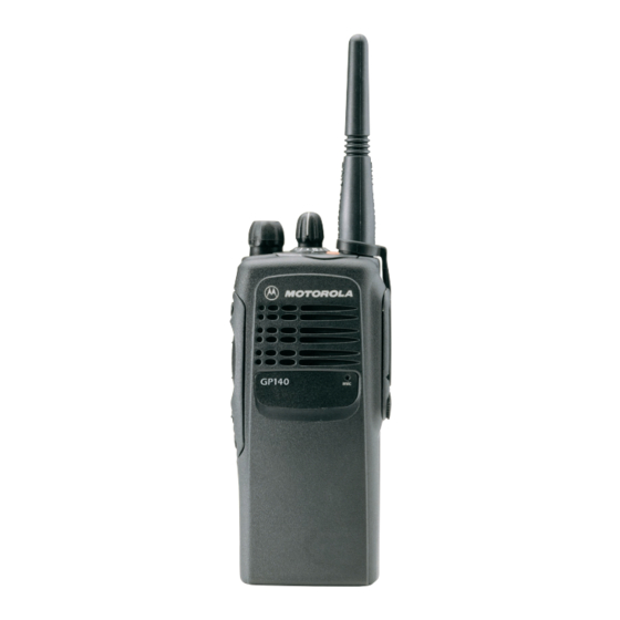
Motorola Professional GP640 Informacje o usłudze
1.0

Allocation of Schematics and Circuit Boards

1.1
Controller Circuits
The VHF circuits are contained on the printed circuit board (PCB) which also contains the Controller
circuits. This Chapter shows the schematics for the VHF circuits only, refer to the Controller section
for details of the related Controller circuits . The PCB component layouts and the Parts Lists in this
Chapter show both the Controller and VHF circuit components. The VHF schematics and the related
PCB and parts list are shown in the tables below.
1.2
Voice Storage Facility
The Voice Storage facility is fitted to the GP1280 radio as standard and the schematics, component
layout and parts list for these circuits are shown in this Chapter. The Voice Storage facility may be
fitted to other radios in the GP Series as an option board; reference must be made to the Option
Board manual in this case. The Voice Storage schematic and the related PCB is shown in Table 4-2
below.
PCB :
SCHEMATICS
Parts List
VHF PCB/SCHEMATICS/PARTS LISTS
Table 4-1 VHF Diagrams and Parts Lists
8486062B12 Main Board Top Side
8486062B12 Main Board Bottom Side
8486062B14 Main Board Top Side
8486062B14 Main Board Bottom Side
Controls and Switches
Receiver Front End
Receiver Back End
Synthesizer
Voltage Controlled Oscillator
Transmitter
8486062B12
8486062B14
Page 4-3
Page 4-4
Page 4-23
Page 4-24
Page 4-5
Page 4-6
Page 4-7
Page 4-8
Page 4-9
Page 4-10
Page 4-11
Page 4-25
Chapter 4