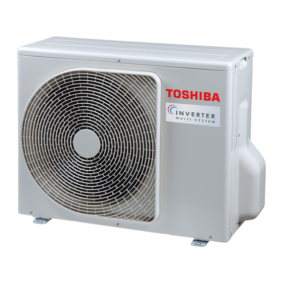
Toshiba 13344 Instrukcja instalacji - Strona 10
Przeglądaj online lub pobierz pdf Instrukcja instalacji dla Klimatyzator Toshiba 13344. Toshiba 13344 18 stron.

Outdoor Unit
5
Installation of outdoor unit
Installation Location
• A place which can bear the weight of the outdoor unit and does not cause
an increase in noise level and vibration.
• A place where the operation noise and air discharge do not disturb
neighbours.
• A place which is not exposed to strong wind.
• A place free of combustible gas.
• A place which does not block a passageway.
• A place where the drain water does not cause any problems.
• A place where there are no obstructions near its air intake or air discharge.
Installation in the following places may result in trouble:
• A place with a lot of machine oil.
• A place with saline-rich atmosphere such as a coastal area.
• A place with high level of sulfi de gas.
• A place where high-frequency waves are likely to be generated, such as
from audio equipment, welders, or medical equipment.
Do not install the unit in such places.
CAUTION
When the outdoor unit is installed in a
place where the drain water might cause
any problems, Seal the water leakage
point tighty using a silicone adhesive or
caulking compound.
Precautions for Installation
• When the outdoor unit is to be installed in an elevated position, be sure to
secure its feet.
• If the outdoor unit is to be mounted on a wall, make sure the base plate
supporting it is sturdy enough.
• The base plate should be designed and manufactured to maintain its
strength over a long period of time, and suffi cient consideration should be
given to ensure that the outdoor unit will not fall.
• When the outdoor unit is installed in a place that is always exposed to
strong wind such as a coastal area or on a high story of a building, secure
the normal fan operation using a duct or a wind shield.
• Especially in windy areas, install the unit in such a way as to prevent the
admission of wind.
• When the outdoor unit is to be mounted high on a wall, take particular care
to ensure that parts do not fall, and that the installer is protected.
• When doing installation work at ground level, it is usual to make wiring and
pipe connections to the indoor units fi rst, and then to make connections to
the outdoor units.
However, if outdoor work is diffi cult, you can change the procedure.
For example, by making adjustments to the wiring and piping lengths on
the inside (rather than the outside).
• When using an air conditioner under low outside temperature conditions
(Outside temp: -5 °C or lower) In COOL mode, prepare a duct or wind
shield so that it is not affected by the wind.
Necessary Space for Installation
If you need to install the outdoor unit in a location where there are some
obstructions or a wall, secure suffi cient space as shown in the fi gure below.
The cooling/heating effect may be reduced by 10%.
Draining Off the Water from the Outdoor Unit
Install 2 waterproof rubber caps and the drain nipple to drain off the
water from the outdoor unit.
• Seal the knock-out holes and screw/thread areas tightly using a silicon
adhesive or a caulking compound.
• Use a drain pan to apply a centralized drain.
Drain nipple
Installation in Regions with Snowfall and Cold Temperatures
Do not use waterproof rubber caps or a drain nipple.
• If you need to install the outdoor unit in a location where there is a
possibility of the drain freezing, pay close attention so that the drain does
not become frozen.
• To protect the outdoor unit from snow, install the outdoor unit on a holding
frame, and attach a snow protection hood and plate.
• Keep the outdoor unit at least 500 mm above the snow accumulation line.
Front
Anchor bolts
Fixing the Outdoor Unit
Fix the outdoor unit using attachment bolts.
• Use 8 mm or 10 mm anchor bolts and nuts.
• Do not allow the attachment bolts to protrude by more than 15 mm.
• Install the outdoor unit at ground level.
• Attach the vibration-proof rubber pads under the fi xing legs.
Drain nipple mounting hole
100
600
Drain hole
GOOD
Absorb vibration
with vibration-proof
rubber pads
Mounting
leg
Foundation
Bottom plate of
outdoor unit
Foundation
Support the bottom surface of the mounting
leg that is in contact with and underneath the
bottom plate of the outdoor unit.
9
Installation Manual
Water-proofi ng rubber cap
Snow protection plate
Snow protection hood
At least 500 mm
Snow accumulation line
Holding frame
508
99
15 mm or
less
BAD
Do not support
the outdoor unit
only with the
If only the end of
mounting leg.
the mounting leg
is supported, it
may deform.
Foundation
