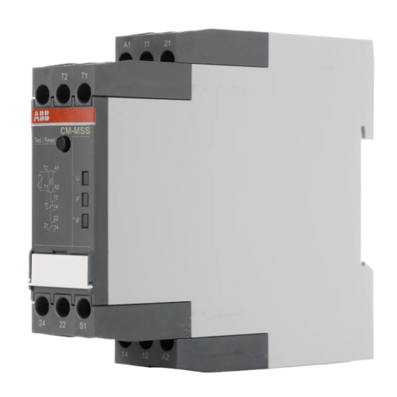
ABB CM-MSS.33 Instrukcja bezpieczeństwa - Strona 9
Przeglądaj online lub pobierz pdf Instrukcja bezpieczeństwa dla Przekaźniki ABB CM-MSS.33. ABB CM-MSS.33 20 stron. Thermistor motor protection relays

I Front view with operating controls
a Indication of operational states with LEDs
U: green LED
- Status indication of control supply
voltage
F: red LED
- Fault message
R: yellow LED
- Status indication of the output relays
b Test / Reset
Reset = Confirm a rectified fault, reset device after test
routine, or confirm a change of configuration
LEDs, statuts information and fault messages (in
order of priority)
CM-MSS.12/13/22/23:
Operational state
Absence of control
supply voltage
Overtemperature
No fault
CM-MSS.11/21:
Operational state
Absence of control
supply voltage
Internal fault
1)
1)
Internal fault
Control supply voltage not
within tolerance range
2)
Short circuit
Interrupted wire
Overtemperature
No fault
1) Restart the device. If after restart the same fault is indica-
ted, replace the device.
2) only CM-MSS.21
CM-MSS.31/32/33/41:
Operational state
Absence of control
supply voltage
Internal fault
1)
Internal fault
1)
Control supply voltage not
within tolerance range
Short circuit
Interrupted wire
Overtemperature
Fault rectified but
not confirmed
Test function
Change of configuration
not confirmed
No fault
1) Restart the device. If after restart the same fault is indica-
ted, replace the device.
2) Depending on the fault with the highest priority
In case of several faults, the fault with the higher priority is
shown.
U:
F:
green
red LED
LED
OFF
OFF
V
V
OFF
V
U:
F:
R:
green
red LED
yellow LED
LED
OFF
OFF
OFF
OFF
W
W
X
X
X
OFF
X
V
OFF
V
Y
OFF
V
Z
OFF
V
V
OFF
V
V
U:
F:
R:
green
red LED
yellow LED
LED
OFF
OFF
OFF
OFF
W
W
X
X
X
OFF
X
V
OFF
V
Y
OFF
V
Z
OFF
V
V
--
2)
V
X
OFF
OFF
X
OFF
V
X
OFF
V
V
CM-MSS.51:
Operational state
Absence of control
supply voltage
Internal fault
1)
Internal fault
1)
Control supply voltage not
within tolerance range
Short circuit
Interrupted wire
Measuring circuit 2:
Overtemperature
Measuring circuit 1:
Overtemperature
Fault rectified but
not confirmed
Test function
Change of configuration
not confirmed
No fault
1) Restart the device. If after restart the same fault is indicated,
replace the device.
2) Depending on the fault with the highest priority
In case of several faults, the fault with the higher priority is
shown.
II DIP switch functions (CM-MSS.41/51)
c DIP switches for the adjustment of:
1
ON
= Non-volatile fault storage OFF
OFF = Non-volatile fault storage ON
2
ON
= Short-circuit detection OFF
OFF = Short-circuit detection ON
3
CM-MSS.41: no function
CM-MSS.51:
ON
= Single evaluation (2x1 c/o contact)
OFF = Accumulative evaluation (1x2 c/o contacts)
4
ON
= Remote Test/Reset
OFF = Remote Reset
Default setting: All DIP switches in position OFF
A change of the DIP switch settings is signaled by the
corresponding LED code. However, only actuating the Test /
Reset button or a restart will confirm the change of configuration.
III DIP switch position (CM-MSS.41/51)
Attention:
In case of switching currents > 2 A, lateral spacing to other units
has to be min. 10 mm (0.39 in).
With products that are used following the ATEX guideline
2014/34/EU, attention should be paid to the attached
instruction sheet „Additional information and notes on safety".
IV Connection diagrams
Series connection of 1 to max. 3 sensors type A per sensor
circuit.
Max. total PTC resistance 750 Ω.
The sensor circuit must not be earthed.
U:
F:
R:
green
red LED
yellow LED
LED
OFF
OFF
OFF
OFF
W
W
X
X
X
OFF
X
V
OFF
V
Y
OFF
V
Z
OFF
V
W
OFF
V
V
--
2)
V
X
OFF
OFF
X
OFF
V
X
OFF
V
V
Page 9/20
English
