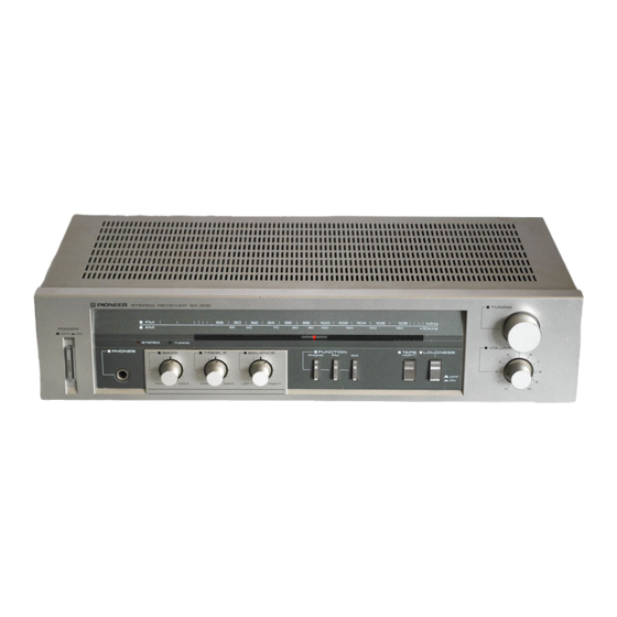
Pioneer ARP-230-0 Instrukcja serwisowa - Strona 6
Przeglądaj online lub pobierz pdf Instrukcja serwisowa dla Odbiornik Pioneer ARP-230-0. Pioneer ARP-230-0 22 stron.

5 . C I R C U I T D E S C R I P T I O N S
FM Front End
A unitized variable capacitor type front end
unit is used consisting of an FET RF single stage
amp, Iocal oscillator/mixer IC and €rn IF trans-
former.
FM lF Amp, Detector and MPX Circuit
A 2-transistor IF amp with ceramic filter is used
and the next stage has an IC (M51533L) contain-
ing the FM IF detector and MPX circuit. The block
diagram of IC M51533L is shown in Fig. 5-1. This
IC uses a peak detection method which can be
adjusted with a single coil. The PLL method is
employed to reconstitute the 38kHz sub-carrier
for the MPX circuit.
The IF signal is input at pin 1 and the detection
output is obtained from pin 5. The detection out-
put passes through the muting Q4, goes to pin 9,
passes through the MPX circuit and the stereo
signals are obtained from pins 11 and L2. In
addition, this unit detects the presence or absence
T
L O U T
R O U T
of a pilot signal to automatically switch between
stereo and mono reception by R14 which is con-
nected to pin 14. When a stereo signal is received,
pin 13 drops to the low level to light the stereo
indicator. When pin 2 is grounded, the PLL VCO
and FM IF operation stop (for AM).
FM Muting and LED Driver
With this unit, muting is automatically activated
when the antenna input drops below 10pV. As the
antenna input decreases, the voltage at pin 3
drops, Q5 is turned off and Q6 is turned on. As a
result, the gate voltage of Q4 drops, Q4 is turned
off and the detector output circuit is blocked
(Fig. 5-1). When an FM or AM station is tuned
in, the base potential of Qb is raised, Q5 is turned
on and the tuning indicator lights.
M 5 r 5 3 3 L
R E G U L A T O R
L E V E L
M E T E R
C I R C U I T
I N P U T
B U F F E R
S T E R E O
S W I T C H
A M
s t - 3
F i g . 5 - 1
F M l F , D e t e c t o r a n d M P X c i r c u i t
