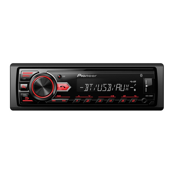
Pioneer MVH-295BT Instrukcja serwisowa - Strona 25
Przeglądaj online lub pobierz pdf Instrukcja serwisowa dla Odbiornik Pioneer MVH-295BT. Pioneer MVH-295BT 25 stron. Digital media receiver

5
12. ELECTRICAL PARTS LIST
NOTE:
Parts whose parts numbers are omitted are subject to being not supplied.
The part numbers shown below indicate chip components.
Chip Resistor
RS1/_S___J,RS1/__S___J
Chip Capacitor (except for CQS.....)
CKS....., CCS....., CSZS.....
Parts marked by " * " are generally unavailable because they are not in our Master Spare Parts List.
The > mark found on some component parts indicates the importance of the safety factor of the part.
Therefore, when replacing, be sure to use parts of identical designation.
The expression of the unit in this manual is shown by u instead of . Please do not make a mistake.
Circuit Symbol and No.
Unit Number :
Unit Name
: MAIN BOARD PCB
A
Unit Number :
Unit Name
: MAIN BOARD PCB
MISCELLANEOUS
U 4
Power Amp IC
FU1
Poly Switch
EN100
Rotary Encoder
5
6
Part No.
PA2032A
144800010012
121658000198
MVH-290BT/XEUC
6
7
7
8
A
B
C
D
E
F
25
8
