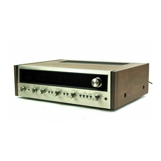
Pioneer SX-727 Instrukcja obsługi - Strona 13
Przeglądaj online lub pobierz pdf Instrukcja obsługi dla Odbiornik Pioneer SX-727. Pioneer SX-727 17 stron. Solid state am/fm stereo
Również dla Pioneer SX-727: Instrukcja serwisowa (48 strony)

SPECIFICATIONS
FETs .
.
..4
lCs. . .
. .
.4
POWER
AMPLIFIER
SECTION
Music Power
Output
(lHF)
195
Watts
(4f/)
i 22
Watts
(BQ)
6ew/6ew
(4s))
4BW/4BW
(BO)
50w +
50w
(4s])
40w
+
40w
(8s))
37W
+
37W
{852,
Harmonic
Distortion
iess
than
O.5"/")
Less
than
A.5% (Continuous
power
output)
Less
than
0.03% (BQ,
24W
I
24W
power
output)
Less
than
A.5Yo
(Continuous
power
output)
Less
than 0.03%
$A,24Wl
24W
power
output)
Power
Bandwidth
(lHF)
10
Hz
to
G0
kHz
(Bf/,
Har-
monic Distortion
less
tharr
Frequency
Response
o.5%)
7 Hz
ro 80 kHz,
ti
dB
lnput
Sensrtivity/lmpedance 500mV/50kS)
(1kHz,
ContinuoLls
power output)
TJIONEEfiI
Continuous
Power
Output
(
1
kHz:each channel driven)
Continuous
Power
Output
(
1
kHz:
both
channel driven)
Power
Output
in the
range
or
2OHz
to 20kHz
(both
channels driven)
Harmonic Distortion
I
ntermodulation
D
istortion
Spea
kers
Damping Factor
PREAMPLIFIER SECTION
Output
Voltage
Harmonic Distortion
Frequency
Response
I
nput Sensitivity/l
mpedance
(1kHz,
for
rated
output)
Recording
Output
BASS
Control
TR
EB
LE Control
LOW
Filter
HIGH
Filter
Equalization
Curve
Loudness
Contour
Transistors. .
5b
Diodes.....34
4
to
16f/
40 (Bfr, lkHz)
500mV (Rated output),
4V
(Max.)
Less
than
0.1%
10Hz
to20
kHz,tl
dB
PHONO
1
MAG
3mV/50kf/
PHONO 2
MAG
3mV/50kO
MIC
2.7mY /50kS/
AUX
200mV/100kf)
TAPE
MONITOR
1,
2
2OOnV
l100kf/
TAPE
REC
i,
2
(Pin iack)
200mV
TAPE
REC
(DlN
connector)
35mV
-
10
dB,
+10
dB/100H2
-
10
dB,
+10
dB/10kHz
-
B
dB
l50Hz
(6
dB
/oct.)
I
dB/10kHz
(6
dB/oct.)
PHONO:
RIAA
S.T.D.
+10 dB/100H2, +6 dB/10kHz
with
Volume
Control set
at
-40
dB position.
Muting
Hum and Noise
(lHF)
FM TUNER SECTION
Frequency
Range
Usable
Sensitivity
(lH
F)
Capture
Ratio (lHF)
Selectivity
(lHF)
lmage Rejection
lF
Rejection
Spu
rious
Rejection
AM
Suppression
Signal-to-Noise Ratio
Harmonic Distortion
Tuning lndicator
Muting
Stereo Separation
Su
b Carrier
Suppression
Antenna
lnput
AM TUNER
SECTION
Frequency
Range
Usable
Sensitivity
(lH
F)
Selectivity
(lHF)
lmage Rejection
lF
Rejection
Signal-to-Noise Ratio
Antenna
MISCELLANEOUS
Power'Requirements
Power Consumption
AC Outlets
Dimensions (overall)
Weight
Without
package
With
package
F
u
rn
ished
Parts
FM
T-type Antenna
F
uses
1
.5A
(5 line voltage
model only)
3A
20
dB
PHONO
More
than 85
dB
AUX
More
than
95
dB
BBMHz
to
108MHz
B7.SMHz
to
108MHz
(FTZ
approved)
1.8
pV
2.0
dB
More
than
70
dB
More
than
85
dB
(9BMHz)
More
than
100
dB
(90MHz)
More
than
90
dB
(9BMHz)
50
dB
70
dB
Mono:
Less
than
0.3%
(1O0%
Mod.)
Stereo:
Less
than
0.5% (100%
Mod.)
Signal
strength
type
and
Cen-
ter tuning
type
Switchable
to
ON-OF
F
More
than 40
dB
(1kHz)
More
than
50
dB
lmpedance
300S/ balanced
and
75f,)
unbalanced.
525kH
z
to
1,605kH2
i0
pV
More
than 35
dB
More
than
80dB
(1,000kH2)
More
than
75
dB
More
than
50
dB
Built-in
ferrite
loopstick
an-
ten na
12AV
60H2,
or
1
10V,
1
2OV
,
130V,
220V
and
24OV (switchable)
50-
60Hz
27Ow (Max.)
Switched
1,
Unswitched
2.
19-1
I
16in./485mm (width)
5-7
l9in.
I
150mm
(
height)
15-3
l9in. 1390mm
(depth
)
30
lb
14
ozl14ks
37
lb
8
ozl17
kg
1
Speaker
Plug
6
1
Pol
ish
ing
cloth
1
Operating
instructions
1
2
NOTE:
Specif
ications
and the
design
subject
to
possible modif
i
cations
without
notice
due
to
imorovements
r4
