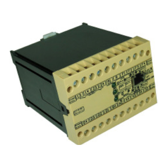
DINA Elektronik DNDS 2C Oryginalna instrukcja obsługi - Strona 11
Przeglądaj online lub pobierz pdf Oryginalna instrukcja obsługi dla Jednostka dystrybucji zasilania DINA Elektronik DNDS 2C. DINA Elektronik DNDS 2C 20 stron.

Instruction manual DNDS Kompakt
Reaction times
The total reaction time is the sum of:
Reaction time of the motion monitor
•
De-energisation time of the output relay (<20ms).
•
Delay of de-energisation on any external switching devices.
•
The reaction time of the motion monitor decreases as the speed to be monitored increases (linear).
It measures at 5 Hz about 200 ms and at 800 Hz about 1 ms
Installation of DNDS 1C, 1D, 1EA, 1GA
The equipment must be cabinet mounted min. IP 54). The Equipment is equipped with a latch for DIN-rail at-
•
tachment.
Supply operating voltage of 24V to terminals A1 (+) and A2 (-). Connect button (reset fault memory) to terminal
•
A2.
Input circuit: DNDS 1C, 1D
•
- Proximity sensor (PNP):
Connect output of the first proximity sensor to IN1 and the 2nd to IN2. Both proximity sensors should be con-
nected to supply voltage A1 and A2.
- Encoder with DNIA adaptor:
Connect output IA1 of the DNIA to terminal IN1; connect output IA2 of the DNIA to terminal IN2; A1 of both
units should be connected together.
Programming
•
- rpm setting: Connect 24 VDC to the terminals D1-D4 according to desired rpm (see table 1).
- Reduction in %: Connect 24 VDC to the terminals F1-F4 according to table 2.
Input circuit: DNDS 1FA, 1GA
•
Connect the Equipment by using a DNDA 15/8 or DNDA 25/8 adapter cable to the encoder.
-
Please note for operation
To prevent a welding together of the contacts, a fuse (6 A slow acting) must be connected before the output
•
contacts.
The total of the reaction times must not lead to a dangerous status.
•
Use copper wiring that will withstand 60/75° C.
•
Tighten screws to terminals with 0.8 Nm max.
•
Important details in the section "Technical Data" should be noted and adhered to.
•
Faults - Errors of DNDS 1C, 1D, 1FA, 1GA
Welding of one contact makes it impossible for the other contact to be switched on.
•
LED "SPEED" and "STOP" do not light:
•
A PNP proximity sensor failure.
PNP proximity sensor not connected.
PNP proximity sensor is not installed on the tooth wheel.
There is a line break to the DNIA.
The encoder is not connected.
LED "SPEED" flashes with 1 Hz interval:
•
The peripheral equipment belonging to input IN2 is defective or there is a line break at that input, or Track A of
the encoder is missing.
LED "STOP" flashes with 1 Hz interval:
•
The peripheral equipment belonging to input IN1 is defective or there is a line break at that input or Track B of
the encoder is missing.
To reset the error disconnect the operating voltage for at least 2s (disconnect A1)
LED "STOP" and LED "SPEED" flashes in 2 Hz intervals:
•
R and SH connected to 24V simultaneously.
DNDS 1C disturbance.
Error by improperly installed external signal lines.
The fault can possibly be eliminated by interruption of the operating voltage for at least 2s (disconnect A1).
Products: safety
technique
DNDS KOMPAKT
Version 04 / 2011.03.16
page 11 from 20
