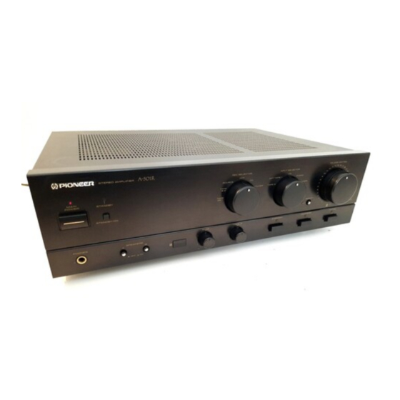
Pioneer A-550R/HE Instrukcja serwisowa - Strona 10
Przeglądaj online lub pobierz pdf Instrukcja serwisowa dla Wzmacniacz Pioneer A-550R/HE. Pioneer A-550R/HE 27 stron.

A-SSOR,
A-450R
3.
P.C.
BOARDS
CONNECTION DIAGRAM
NOTE
1.
This P.C.B connection diagram
is
viewed
from
the
parts
mounted
side.
2.
The
parts
which
have been
mounted on
the
board can
be replaced
with those
shown
with
the corresponding wiring
symbols
listed in
the following Table.
P.C.B. pattern
diagram
indication
Corresponding
part
symbol
Part
Name
/Q504
n
EO
O
O
Pil
-p£n
e6
q
'
5
Transistor
Q21
5
—
O
O
O
Radiator type
transistor
®-°
203
o
D203
O
M
o
Diode
o
R237
o
R237
o
WV
o
Resistor
/C513
\
\
J
Capacitor
(Polarity)
4
J
o
—
|
|—
o
j
Capacitor
(Non-polarity)
Others
P.C.B. pattern
diagram
indication
Part
Name
1C
1C
S
Switch
RY
Relay
L
Coil
F
Filter
VR
Variable
resistor
or
Semi-fixed
resistor
3.
The
capactor
terminal
marked
with
©(double
circles)
shows
negatine termianl.
4.
The
diode
terminal
marked
with
©
(double
circles)
shows
cathode
side.
5.
The
transistor
terminal to
which E
is
affixed
shows
the
emitter.
1
2
