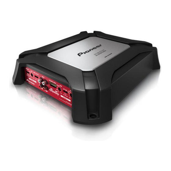
Pioneer GM-6500F/XZEW5 Instrukcja serwisowa - Strona 22
Przeglądaj online lub pobierz pdf Instrukcja serwisowa dla Wzmacniacz Pioneer GM-6500F/XZEW5. Pioneer GM-6500F/XZEW5 30 stron. Bridgeable four-channel power amplifier

1
11. PCB CONNECTION DIAGRAM
11.1 PCB KIT
A
NOTE FOR PCB DIAGRAMS
1.The parts mounted on this PCB
include all necessary parts for
several destination.
For further information for
respective destinations, be sure
to check with the schematic dia-
gram.
2.Viewpoint of PCB diagrams
Capacitor
Connector
B
Chip Part
P.C.Board
C
D
E
F
A
22
1
2
A
PCB KIT
SIDE A
SIDE B
GM-6500F/XZUC
2
3
3
4
4
