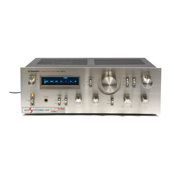
Pioneer SA-7800 Instrukcja obsługi - Strona 2
Przeglądaj online lub pobierz pdf Instrukcja obsługi dla Wzmacniacz Pioneer SA-7800. Pioneer SA-7800 12 stron.
Również dla Pioneer SA-7800: Instrukcja serwisowa (30 strony)

CONTENTS
Features
Stereo System Composition
Installation Precautions
Rear Panel Facilities
Connections
FEATURES
Power Amp with Ultra-wide-frequency-range
Output and Low Distortion
This amplifier has the impressive feature which is the
NSA
(Non-Switching-Amplifier),
created
specially
by
Pioneer. This is a type of amplifier that adopts the merits of
both the class A and class B amplifiers, and it excels in
keeping down
the heat loss and allows the transistors to
operate all the time in the active region. For this reason, a
high output power with a very low distortion factor is
yielded all the way up to the high frequencies.
Also it is designed to pack a punch at every stage — this
is evident in the first stage differential input, current mirror
load; the predriver stage Darlington, constant-current load;
and the output stage 2-stage Darlington, push-pull output
circuit configuration. All this adds up to a DC amp con-
figuration which uses SL RETs (Super Linear Ring Emitter
Transistors), which have an excellent switching response in
the high frequency range, for the power transistors.
Continuous Power Output is 65watts" per chan-
nel, min., at 8 ohms or 4 ohms from 10 Hertz to
20,000Hertz with no more than 0.009% total
harmonic distortion.
T-shaped
''skyve" heat sink is used
because
it is
lightweight and
it dissipates
the heat very effectively.
Even when the amplifier is operating continuously under
full power conditions, these heat sinks keep the rise in tem-
perature down, and they ensure that a high-quality power is
provided.
Flat Amplifier with High S/N Ratio and Low
Distortion
This model adopts an ICL DC amplifier which is com-
posed of a two-stage differential amplifier for the first stage
using ultra-low-noise dual FETs and an emitter follower for
the final stage. This construction is successful in achieving a
low distortion and a high signal-to-noise ratio, and in main-
taining an S/N ratio of 110dB (AUX).
Operations
Using the Tape Decks
Conditions Frequently Mistaken for
Malfunctions
Specifications
Insertion
Schematic Diagram
Insertion
Highly Reliable Protection Circuits
Phono Interference Filter
Set this switch to the ON
position when the radio-fre-
quency interference is adversely affecting the sound quality
during record play. This action serves to reduce the amount
of noise.
*Measured pursuant to the Federal Trade Commission's Trade Regulation rule on Power Output Claims for Amplifiers,
