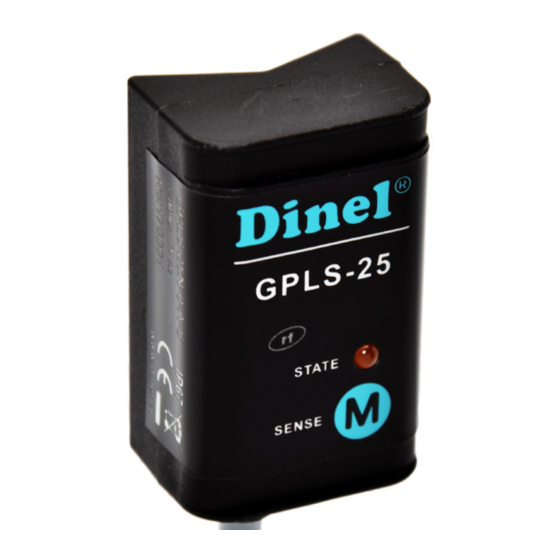
Dinel GPLS-25 Series Instrukcja obsługi - Strona 8
Przeglądaj online lub pobierz pdf Instrukcja obsługi dla Przełącznik Dinel GPLS-25 Series. Dinel GPLS-25 Series 14 stron. Thru-wall level switches
Również dla Dinel GPLS-25 Series: Instrukcja obsługi (12 strony)

b) Mode C (normally closed)
1. Put the level of the measured medium in the state below the lower edge of the sensor in the
tank or in the gauge-pipe.
2. Attach the magnetic pen MP-8 to the sensitive spot
LED lights up, the sensor is in the state closed.
3. After removal of the magnetic pen check the status of orange lights:
-
If the LED lights or is flashing rapidly (0.2 s), go to step 4.
-
If the LED doesn´t light, you must repeat step 2 so as to observe the limit of 4 seconds
attaching magnetic pen.
4. Put the level of the measured medium in the state above the upper edge of the sensor in the
tank or in the gauge-pipe.
5. Attach the magnetic pen MP-8 to the sensitive spot
LED goes out, the sensor is in the state open.
6. After removal of the magnetic pen check the status of orange lights:
- If the LED doesn´t light, settings of the sensor is correct.
- If the LED lights, the sensor was set incorrectly and you must repeat the procedure from
step 1.
- If the LED is flashing, the sensor didn´t recognize upper and lower limits. In this case, first
verify that at the step 1 the level of the measured medium was below the lower edge of the
sensor and at the step 3 the level of the measured medium was above the upper edge of
the sensor. Then make sure that the thickness of the gauge-pipe wall or the tank wall does
not exceed the limit specified in the Technical specifications (p. 2). If not, check there isn´t
a thick layer of sediment on the inner wall of the tank or the gauge-pipe.
After this settings the sensor responds to the level immersion and emersion in the upper half of
the sensing area and the hysteresis size 5 mm (1/8 of the distance between the bottom and the
top of the sensor).
9 . Status signalization
Indicator
Function
Continuous light – Sensor is closed (switched ON)
Dark – Sensor is open (switched OFF)
Orange
Rapid flashing (period 0,2 sec.) *
LED
– Unrecognized upper and lower limits of setting mistake
Slow flashing (period 0,8 sec.) – Short circuit at sensor output
* Sensor with "S" type output, for each flash of the LED switches its output on for approx. 3 ms. This period is suffici-
ently short to avoid unwanted switching of relay contacts. For binary inputs, we recommend to set the filter so as not
to respond to pulses shorter than 3 ms.
8
for minimum 4 seconds. When the
M
for maximum 2 seconds. When the
M
GPLS-25
© Dinel, s.r.o.
