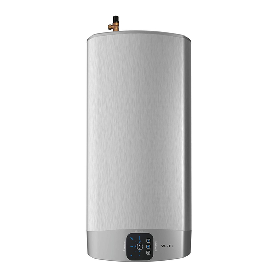
Ariston VLS EVO 80 WiFi Instrukcja montażu i obsługi - Strona 9
Przeglądaj online lub pobierz pdf Instrukcja montażu i obsługi dla Podgrzewacz wody Ariston VLS EVO 80 WiFi. Ariston VLS EVO 80 WiFi 25 stron. Unvented water heater

If the supplied Dielectric Junctions are not fi tted this could void the warranty.
Only the use of copper pipe is recommended for connection to the heater. If any other material is
used it must be able to withstand 90°C at 7 bar pressure for long periods.
No valve must be fi tted between the expansion/pressure relief valve and the water heater.
All other required safety components to install the appliance are supplied as a kit with the appliance:
15 mm pressure reducing valve set at 3.5bar. Expansion vessel (charge pressure set at 3.5bar)"
DISCHARGE PIPE WORK NOTE:
The following guidelines refer to Building Regulation G3. It is good practice to follow these guide-
lines for all relief valve discharge pipe work.
1) The tundish must be vertical and fi tted within 600 mm of the temperature & pressure relief valve and
must be located with the cylinder. The tundish must also be in a position visible to the occupants, and
positioned away from any electrical devices. The discharge pipe from the tundish should terminate in
a safe place where there is no risk to persons in the vicinity of the discharge and to be of metal.
2) Discharge pipes from the temperature & pressure relief and pressure relief valve may be joined
together.
3) The pipe diameter must be at least one pipe size larger than the nominal outlet size of the safety de-
vice unless its total equivalent hydraulic resistance exceeds that of a straight pipe 9 m long.
i.e. Discharge pipes between 9 m and 18 m equivalent resistance length should be at least 2 sizes
larger than the nominal outlet size of the safety device. Between 18 m and 27 m at least 3 times larger,
and so on.
Bends must be taken into account in calculating the fl ow resistance.
See the following fi gure and the Table 2.
4) The discharge pipe must have a vertical section of pipe at least 300 mm in length, below the tundish
before any elbows or bends in the pipe work.
5) The discharge pipe must be installed with a continuous fall.
6) The discharge must be visible at both the tundish and the fi nal point of discharge, but where this is
not possible or practically diffi cult; there should be clear visibility at one or other of these locations.
Examples of acceptance are:
i) Ideally below a fi xed grating and above the water seal in a trapped gully.
ii) Downward discharges at a low level; i.e. up to 100 mm above external surfaces such as car parks,
hard standings, grassed areas etc. These are acceptable providing that where children may play or
otherwise come into contact with discharges, a wire cage or similar guard is positioned to prevent
contact, whilst maintaining visibility.
iii) Discharges at high level; i.e. into a metal hopper and metal down pipe with the end of the discharge
pipe clearly visible (tundish visible or not). Or onto a roof capable of withstanding high temperature
discharges of water 3 m from any plastic guttering systems that would collect such a discharge
(tundish visible).
9 / EN
