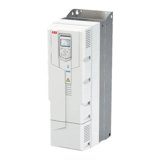
ABB ACH580-31 Instrukcja szybkiej instalacji i uruchomienia - Strona 13
Przeglądaj online lub pobierz pdf Instrukcja szybkiej instalacji i uruchomienia dla Jednostka sterująca ABB ACH580-31. ABB ACH580-31 16 stron. Converter modules with electrolytic dc capacitors in the dc link
Również dla ABB ACH580-31: Podręcznik (16 strony)

ACQ580
Input rating
-31-...
Frame
NEC
size
I
ratings
1
A
U
= 3-phase 480 V
n
07A6-4
R3
7.0
012A-4
R3
9.0
014A-4
R3
12.0
023A-4
R3
17.0
027A-4
R6
24
034A-4
R6
29
044A-4
R6
34
052A-4
R6
44
065A-4*
R6
54
077A-4*
R6
66
096A-4
R8
82
124A-4
R8
111
156A-4
R8
134
180A-4
R8
163
* These ratings are not to be used for drives with degree of protection of IP55 (UL Type 12) option +B056.
Terminal data
Cable entries
Max. cable
Frame size
diameter
pcs
mm
R3
3
23
R6
3
45
R8
3
45
For tightening torques of grounding terminals, see section
* Maximum cable diameter accepted.
Notes:
•
The minimum specified wire size does not necessarily have sufficient current carrying capacity at maximum load. Make
sure the installation complies with local laws and regulations.
•
For IEC installations using mm
recommended wire size. For NEC installations using AWG cable, this applies only to the R8 frame 206A drive.
•
The maximum number of conductors per terminal is 1.
Dimensions, weights and free space requirements
Frame
Weight
size
kg
IP21, UL Type 1
R3
21.3
R6
61.0
134.51
R8
118
260.19
IP55, UL Type 12 (option +B056)
R3
21.3
R6
63.0
138.92
R8
124
273.42
200 mm (7.9 in) free space is required at top of the drive.
300 mm (11.8 in) free space (when measured from the drive base without the cable box) is required at bottom of the drive.
Ambient conditions
Installation altitude
Surrounding air temperature
Output ratings
I
2
A
7.6
12.0
14.0
23.0
27
34
44
52
65
77
96
124
156
180
L1, L2, L3, T1/U, T2/V, T3/W, UDC+ and UDC- terminals
*
2
in
mm
0.91
0.5...16.0
1.77
6.0...70.0
1.77
25...150
2
cable, the terminals do not accept a conductor that is one size larger than the
Height
lb
mm
46.97
495
771
965
46.97
490
771
965
0 ... 4000 m (0 ... 13123 ft) above sea level. The output current must be derated at
altitudes above 1000 m (3281 ft). The derating is 1% for each 100 m (328 ft) above
1000 m (3281 ft).
Operation: -15 ... +50 °C (5 ... 122 °F). Frost is not permitted. The rated output current
must be derated by 1% for each 1 °C (1.8 °F) over 40 °C (104 °F). Storage (in the package):
-40 to +70 °C (-40 to +158 °F).
Motor
1)
power
UL class T
P
I
Ld
Ld
Bussmann type
A
hp
7.6
5.0
12.0
7.5
14.0
10
23.0
15
27
20
34
25
44
30
52
40
65
50
77
60
96
75
124
100
156
125
180
150
Wire size
AWG
20...6
10...2/0
4...300MCM
Connect the power cables
Width
in
mm
19.49
205
30.35
252
38.01
300
19.29
205
30.35
252
37.99
300
Typical
3)
Fuses
power cable
5)6)7)
Copper
10)
AWG
JJS-15
14
JJS-20
14
JJS-25
14
JJS-35
10
JJS-40
8
JJS-50
8
JJS-60
6
JJS-80
4
JJS-90
2
JJS-110
2
JJS-150
1/0
JJS-200
2/0
JJS-225
4/0
JJS-300
250 MCM
Tightening torque
N·m
1.7
5.6
30
.
Depth
in
mm
8.06
354
9.91
393
11.81
438
8.06
360
9.92
448
11.81
496
13
Typical
power loss
8)
W
219
278
321
473
625
711
807
960
1223
1560
1678
2237
2796
3356
lbf·ft
1.3
4.1
22.5
in
13.93
15.46
17.23
14.17
17.65
19.53
