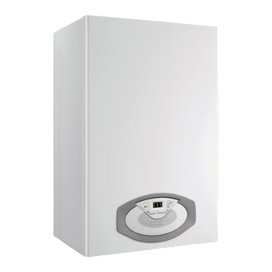
Ariston Clas 24 FF Instrukcje instalacji i serwisowania - Strona 18
Przeglądaj online lub pobierz pdf Instrukcje instalacji i serwisowania dla Kocioł Ariston Clas 24 FF. Ariston Clas 24 FF 40 stron. Wall-hung gas boiler type c
Również dla Ariston Clas 24 FF: Podręcznik użytkownika (10 strony)

messa in funzione
Procedura di accensione
Premere il tasto ON/OFF sul pannello comandi per
accendere la caldaia il display visualizza:
La modalità di funzionamento verrà visualizza dalle tre cifre
evidenziate nel disegno sopra riportato:
la prima cifra indica la modalità di funzionamento:
0 = Stand-by, nessuna richiesta
C = Richiesta riscaldamento
c = Post-circolazione riscaldamento
d = Richiesta acqua calda sanitaria
h = Post-circolazione dopo prelievo sanitario
F = Antigelo circolatore attivo o antigelo bruciatore attivo
la seconda e terza cifra indicano:
- in assenza di richiesta la temperatura di mandata
- in modalità riscaldamento la temperatura di mandata
- in modalità sanitario la temperatura impostata acqua calda
sanitaria
- in modalità antigelo la temperatura di mandata.
Viene inoltre segnalato lo svolgimento di alcune funzioni:
P1 - Ciclo disareazione attivato
P1
Predisposizione al servizio
Per garantire la sicurezza ed il corretto funzionamento dell'apparecchio
la messa in funzione della caldaia deve essere eseguita da un tecnico
qualifi cato in possesso dei requisiti di legge.
Alimentazione Elettrica
- Verifi care che la tensione e la frequenza di alimentazione coincidano
con i dati riportati sulla targa della caldaia
- verifi care l'effi cienza del collegamento di terra.
Riempimento circuito idraulico
Procedere nel modo seguente:
- aprire le valvole di sfogo dei radiatori dell'impianto;
- allentare il tappo della valvola automatica di sfogo aria posta sul
circolatore;
- aprire gradualmente il rubinetto di riempimento della caldaia e chiudere le
valvole di sfogo aria sui radiatori appena esce acqua;
- chiudere il rubinetto di riempimento caldaia quando la pressione
indicata sull'idrometro è di 1-1,5 bar.
Alimentazione Gas
Procedere nel modo seguente:
- verifi care che il tipo di gas erogato corrisponda a quello indicato
sulla targhetta della caldaia
- aprire porte e fi nestre
- evitare la presenza di scintille e fi amme libere
- verifi care la tenuta dell'impianto del combustibile con rubinetto di
intercettazione posto in caldaia chiuso e successivamente aperto
con valvola del gas chiusa (disattivata), per 10 minuti il contatore
non deve indicare alcun passaggio di gas.
Prima accensione
1. Assicurarsi che:
-
il rubinetto gas sia chiuso;
-
il collegamento elettrico sia stato eff ettuato in modo corretto.
Assicurarsi in ogni caso che il fi lo di terra verde/giallo sia collegato
ad un effi ciente impianto di terra.
-
sollevare, con un cacciavite, il tappo della valvola sfogo aria
automatica;
-
l'indicazione della pressione d'impianto sul manometro sia
superiore a 1 bar;
18
commissioning
Ignition procedure
Press the ON/OFF button on the control panel
to switch on the boiler. The display shows:
The operating mode will be indicated by the three fi gures marked
out on the diagram above.
The fi rst fi gure indicates the operating mode:
0 XX -
Stand-by
C XX - Central heating request
c XX - Heating post-circulation
d XX - Domestic hot water request
h XX - hot water post-circulation
F XX - circulation pump anti-freeze protection enabled
- burner anti-freeze protection enabled
The second and third fi gures indicate:
- the fl ow temperature when no heating requests have been made
- the fl ow temperature in central heating mode
- the temperature of the hot water in domestic hot water
- the fl ow temperature in anti-freeze mode.
The carrying out of certain functions is shown:
P1 - = Deaeration cycle started
P1
Initial procedures
To guarantee safety and the correct operation of the appliance, the
boiler must be prepared for operation by a qualifi ed technician who
possesses the skills which are required by law.
Electricity supply
- Check that the voltage and frequency of the electricity supply
correspond to the data shown on the boiler data plate;
- Make sure that the earthing connection is effi cient.
Filling the hydraulic circuit
Proceed in the following manner:
- Open cold water inlet tap;
- Lift the cap on the automatic air relief valve on the circulation
pump;
- Gradually open the valve under the boiler
- Open each air release tap starting with the lowest point and close it only
when clear water, free of air, is visible.
-
Clause the valve under the boiler when at least 1 bar registers on
the pressure gauge.
Gas supply
Proceed in the following manner:
- make sure that the main gas supply uses the same type of gas as
indicated on the boiler data plate;
- Open all doors and windows;
- Make sure there are no sparks or naked fl ames in the room;
- Make sure that the system does not leak fuel using a cut-off valve
inside the boiler itself which should be closed and then opened
while the gas valve is disabled. The meter must not show any signs
of gas being used for 10 minutes.
First ignition
1. Make sure that:
- The gas valve is closed;
- The electrical connection has been properly carried out. Make
sure that, in any case, the green/yellow earthing wire is connected
to an effi cient earthing system;
- Use a screwdriver to lift the cap on the automatic air relief valve;
-
the system pressure is at least 1 bar on the pressure gauge
