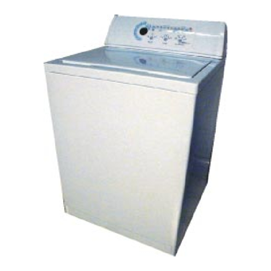
Whirlpool CATALYST Instrukcja rozwiązywania problemów i naprawy - Strona 33
Przeglądaj online lub pobierz pdf Instrukcja rozwiązywania problemów i naprawy dla Spryskiwacz Whirlpool CATALYST. Whirlpool CATALYST 45 stron. Electronic three-speed automatic washers with catalyst cleaning action
Również dla Whirlpool CATALYST: Instrukcja obsługi i konserwacji (15 strony)

2.
If the resistance is outside of range, replace the valve assembly.
Test #3 - Off-Balance Solenoid Switch Test
1.
Unplug the washer and disconnect connectors P5 and P6 from the control board before check-
ing the resistance. Make the checks at contacts shown. NOTE: Off balance arm must be
depressed to read solenoid resistance. Move basket to rear of unit to actuate arm.
SOLENOID
Off Balance
Test #4. Motor Control System Test
This test checks that the appropriate relays are delivering voltage to the motor and
that the wiring connections from the control board to the motor are good.
1.
See the Pressure Transducer / Agitate Test in the Service Diagnostic Tests table.
As test progresses, 110 - 125 VAC should be measured across the following test points for
each agitation speed.
High Speed
Medium Speed
Low Speed
2.
If 110 - 125 VAC is not measured across any of the points, replace the control board.
3.
If 110 - 125 VAC is measured across these points but the motor does not run, go to the motor
test. This test will check the wiring to the motor and the motor.
Alternate Motor Test
1.
Unplug the washer. Check resistance of Low, Med, and High speed motor windings as shown
in the chart. Note: The start winding coil must be checked at the motor.
WINDING
Medium
2.
If the measurement shows infinite ohms, there is either an open circuit in the motor winding or
in the connection between the control board and the motor. To locate the open circuit, mea-
sure the resistance at the motor instead of across P7 and P9.
3.
If the resistance is still infinite, replace the motor.
4.
If the resistance at the motor test OK, there is an open circuit in the wiring between the
motor and control board. Repair or replace the wiring harness.
RESISTANCE
1200Ω
Coil
Across P9-2 and P7-2
Across P9-2 and P9-1
Across P9-2 and P7-4
RESISTANCE
Low
2.6Ω
1.5Ω
High
2.3Ω
Start
5.1Ω
MEASURE BETWEEN
Lid Sw Harness
P5 contact 3
GY/WH
MEASURE BETWEEN
P7 - 4
P9 - 2
WH/OR
WH/BK
P7 - 1
P9 - 2
OR
WH/BK
P7 - 2
P9 - 2
WH/VT
WH/BK
Measured at the motor across
the RD and YL colored wires.
29
GY
