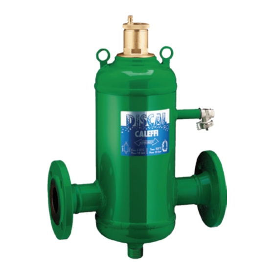
CALEFFI DISCAL 551 Series Podręcznik - Strona 9
Przeglądaj online lub pobierz pdf Podręcznik dla Systemy filtracji wody CALEFFI DISCAL 551 Series. CALEFFI DISCAL 551 Series 12 stron. Air separator
Również dla CALEFFI DISCAL 551 Series: Instrukcja instalacji, uruchomienia i serwisowania (12 strony), Instrukcja instalacji, uruchomienia i serwisowania (12 strony), Instrukcja instalacji, uruchomienia i serwisowania (8 strony)

Procedura di
1. Sfilare le due coperture di testa nere alle
installazione e
di assemblaggio
2. Aprire il tappo superiore (per misure fino a
coibentazione
DN 50 – DN 150
3. Procedere all'installazione del disaeratore
Procedure for
4. Per le misure fino a DN 100 stendere sulle
installation and
insulation
assembly
DN 50 – DN 150
Installation ünd
Montage der
5. Incastrare il tappo superiore su uno dei due
Isolierung
DN 50 – DN 150
6. Riassemblare i due gusci laterali.
Procédure
7. Rifinire la giunzione con la striscia in dotazione
d'installation et
d'assemblage de
8. Completare con le due coperture di testa nere*.
l'isolant
N.B.: Sigillante consigliato: Mastice Superchiaro
DN 50 – DN 150
Procedimiento de
instalación
*Operazioni da non eseguire per i disaeratori DN 125 e DN 150.
y de montaje del
aislamiento
DN 50 – DN 150
1. Extract the black head covers at the two ends*.
2. Open the upper cap (for sizes up to DN 100) and the two side shells.
Procedimento
3. Install the deaerator on the system.
para a instalação
4. For sizes up to DN 100 spread a light layer of sealant onto the
e montagem do
isolamento
DN 50 – DN 150
Plaatsing
5. Fit the upper cap onto one of the two shells and then join on the other one*.
isolatieschalen
6. Reassemble the two side shells.
DN 50 – DN 150
7. Finish the join with the strip provided in the box.
8. Complete with the two black head covers*.
N.B.: Recommended sealant: Mastice Superchiaro our code 615500.
*Operations not to be performed for deaerators DN 125 and DN 150.
1. Die zwei schwarzen Kappen an den Enden abnehmen*.
2. Den oberen Deckel (für Abmessugen bis DN 100) und die zwei
3. Den Luftabscheider in der Anlage installieren.
4. Bei den Größen bis DN 100 an den Flächen A und B eine dünne
5. Den oberen Deckel an einer der zwei Schalenhälfte einsetzen und
6. Die zwei Schalenhälften wieder zusammensetzen.
7. Die Verbindungsstelle mit dem in der Kartonage mitgelieferten Streifen
8. Die zwei schwarzen Kappen wieder schließen*.
Hinweis: Empfohlenes Dichtmittel: Superhelle Dichtmasse, unsere
*Diese Vorgänge sind bei den Luftabscheidern DN 125 und DN 150 nicht
erforderlich.
estremità*.
DN 100) e i due gusci laterali.
sull'impianto.
superfici A e B un leggero strato di sigillante e
attendere che il solvente sia evaporato. Per le
restanti misure DN 125 e DN 150 togliere la
pellicola dell'adesivo già applicato sulle
superfici.
gusci e unire successivamente l'altro*.
nella scatola.
ns. cod. 615500.
surfaces A and B and wait for the solvent to evaporate. For the
remaining sizes DN 125 and DN 150 peel off the film of adhesive
already applied on the surfaces.
Schalenhälften öffnen.
Schicht Dichtmittel auftragen und abwarten, bis das Lösungsmittel
verdampft. Bei den restlichen Größen DN 125 und DN 150 den bereits
an den Flächen angebrachten Film abziehen.
anschließend die andere damit verbinden*.
abdichten.
Art.Nr. 615500.
9
A
B
