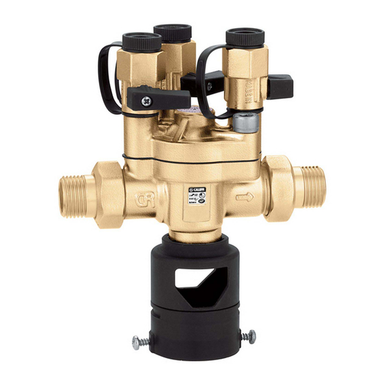
CALEFFI 574 series Podręcznik - Strona 3
Przeglądaj online lub pobierz pdf Podręcznik dla Produkt hydrauliczny CALEFFI 574 series. CALEFFI 574 series 12 stron. Testable, reduced pressure zone backflow preventer
Również dla CALEFFI 574 series: Podręcznik (16 strony)

CAUTION: In the case of highly aggressive water, arrangements must be made to treat the water before
it enters the backflow preventer, in accordance with current legislation. Otherwise the valve may be
damaged and will not operate correctly.
ATTENTION: Dans le cas de l'eau fortement agressifs, des dispositions doivent être prises pour traiter
l'eau avant qu'elle ne pénètre dans le disconnecteur, conformément à la législation actuelle. Sinon la
soupape pourrait être endommagée et ne fonctionnent pas correctement.
Principle of operation
The backflow preventer consists of two check valves (4) and (5), a chamber known as "reduced
pressure area" (B) and of a discharge valve connected to the latter (3). The water entering the backflow
preventer opens the upstream check valve (4) and at the same time through the channel (1) acts
on the diaphragm (2) which closes the discharge valve (3) by means of the rod and then opens the
downstream check valve. The pressure in the intermediate chamber under normal operating conditions
is always less than the upstream pressure by at least 2 psi (140 mbar) as a result of a pre-calculated
pressure loss on the first check valve. This difference in pressure ∆p between the upstream (A) and
intermediate (B) areas can be specified on a safety basis so that in the event of damage occuring, or
a vacuum, the discharge valve is opened when the upstream pressure is still greater than the pressure
in the intermediate area by at least 2 psi (140 mbar). In the event of damage to the diaphragm, the
safety gasket under the thrust of the contrast spring (3) prevents the return of water upstream from
the discharge since there is no more ∆p equilibrium between the two areas.
NOTE: For the code 574050A, to ensure correct operation the air must be released in the upper part
of the diaphragm by means of the relief screw (6).
1
A
4
B
574004A
These codes include factory assembled inlet
and outlet isolation/shut-off ball valves, not
pictured.
LEAVE THIS MANUAL FOR THE USER
LAISSEZ CE MANUEL AVEC L'UTILISATEUR
2
5
3
1
A
4
B
574050A
3
2
6
5
3
