Alderon Industries Sump Advisor 2000559 Skrócona instrukcja obsługi - Strona 2
Przeglądaj online lub pobierz pdf Skrócona instrukcja obsługi dla System bezpieczeństwa Alderon Industries Sump Advisor 2000559. Alderon Industries Sump Advisor 2000559 4 stron. 2-zone alarm and sensor

Step 4: Wiring Auxiliary Dry Contacts
If connecting to an existing alarm security system or building automation system (BAS), leave the positive (+) and negative (-) terminals open and use 18
gauge 2-conductor wire to connect the existing product to terminals 2A, 2B, 1A, and 1B.
If connecting to an Alderon™ auto dialer using the supplied 4-conductor wire: connect red wire to positive (+) terminal, black wire to negative (-) terminal,
yellow wire to terminal 1A, and white wire to terminal 1B.
When the VertiMAC™ pump switch is activated, it will turn the pump on closing the pump auxiliary dry contacts 2A and 2B on the Sump Advisor™ alarm
panel. When the Sump Advisor™ sensor high level alarm float is activated, it will close the alarm auxiliary dry contacts 1A and 1B on the Sump Advisor™
alarm panel.
After the access cover has been removed from the alarm panel, use a needle nose pliers (not included) to remove the desired break away tab(s) from the
access cover. Lightly pull and twist off tab(s). Replace the access cover and run wire(s) through the knockout(s).
AUXILIARY DRY CONTACTS:
Terminals "+" (positive) and "-" (negative)
11.1VDC, 100mA power supply for external equipment
Terminals 2A and 2B
Zone 2 (Pump Run)
Normally Open
Terminals 1A and 1B
Zone 1 (High Sump)
Normally Open
Class 2, 24VDC/VAC (50/60 Hz)
100 Milliamps Maximum
Note: The auxiliary dry contacts of the alarm panel
are normally open ONLY.
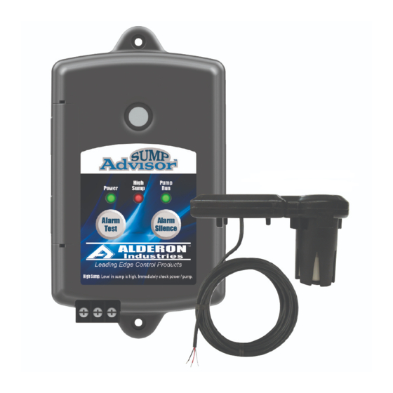
Step 5: Wiring Sump Advisor™ Sensor to Sump Advisor™ Alarm Panel
Connect the normally open Sump Advisor™ sensor (rated 24VDC, 100mA maximum) to the Sump Advisor™ alarm panel for local high level alarm and pump
run indication from the VertiMAC™ pump switch. Connect white wire to terminal W, red wire to terminal R, and black wire to terminal B.
W
R
B
2A 2B 1A 1B
TERMINAL BLOCK CONNECTIONS:
Sensor Wire
Alarm Panel Terminal
White
W = Common
Red
R = High Level Alarm
Black
B = Pump Run
