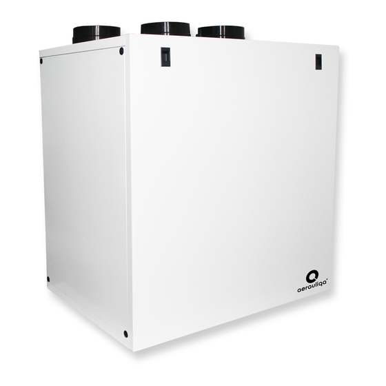
aerauliqa QR590E Instrukcja instalacji - Strona 4
Przeglądaj online lub pobierz pdf Instrukcja instalacji dla Wentylator aerauliqa QR590E. aerauliqa QR590E 20 stron. Energy recovery ventilation unit with enthalpic heat exchanger

Fig. 3.b Connections in RIGHT orientation
Intake air from outside
A
Exhaust air to outside
B
Supply air to inside
C
Extract air from inside
D
To set the RIGHT orientation of the machine:
• Modify the orientation on the CTRL-DSP (point 7.2 - Installer menu: 3 Machine Orientation).
• Move the F7 filter from the left to the right side.
• Replace the ducting connection label on the top of the casing with the one supplied with this installation manual.
3.4 Space required
Make sure that enough space is left around the unit to allow easy maintenance (access to filters, terminal box and removal of the
side and front inspection panels).
3.5 Rating label
Fig.3.c Rating label
4 traNsPort aND storagE
Make sure that specific warnings and cautions in Chapter 2 "Precautions" are carefully read, understood and applied!
The appliance is delivered in one carton box.
The appliance should be stored and transported in such a way that it is protected against physical damage that can harm spigots,
casing, display etc.
It should be covered so that dust, rain and snow cannot enter and damage the unit and its components.
5 INstallatIoN
Make sure that specific warnings and cautions in Chapter 2 "Precautions" are carefully read, understood and applied!
This section describes how to install the unit correctly. The unit must be installed according to these instructions.
5.1 Unpacking
Verify that the unit (and eventual accessories) delivered is according to order before starting the installation. Any discrepancies
from the ordered equipment must be reported to the supplier.
5.2 Where/how to install
• A ll QR units are meant for indoor installation in a heated space.
• M ount the unit on flat surface (wall).
• T he unit must always be installed vertically.
• I t's important that the unit is completely leveled before it is put into operation.
• P lace the unit preferably in a separate room (e.g. storage, laundry room or similar).
• W hen choosing the location it should be kept in mind that the unit requires maintenance regularly and that the inspection doors
should be easily accessible.
• L eave free space for opening the removable panels and for removal of the main components (see 3.4).
• T he outdoor air grilles if possible be put in the northern or eastern side of the building and away from other exhaust outlets like
kitchen fan exhausts or laundry room outlets.
4
C
B
D
A
WARNING
WARNING
