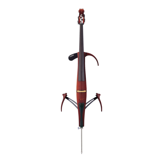
Yamaha Silent Cello SVC210 Instrukcja serwisowa - Strona 14
Przeglądaj online lub pobierz pdf Instrukcja serwisowa dla Instrument muzyczny Yamaha Silent Cello SVC210. Yamaha Silent Cello SVC210 30 stron. Silent electric cello
Również dla Yamaha Silent Cello SVC210: Instrukcja obsługi (15 strony), Instrukcja obsługi (16 strony)

SVC210
I
INSPECTIONS
1.
Preparations
1-1
Unit Setting
Unless otherwise specified, the controls and switches are to be set as follows.
AUX VR
VOLUME
POWER switch
REVERB switch
The [PHONES] and [LINE OUT] terminals are to be terminated with the following resistors.
PHONES
LINE OUT
1-2
Measuring instruments and jigs
The following measuring instruments and jigs are used for inspection.
Measuring instruments : low-freqency oscillator, level meter.
Jigs
2.
Inspections
Items
Output level 1
PHONES (L)
PHONES L
PHONES (R)
Output level 2
PHONES (L)
PHONES R
PHONES (R)
Output level 3
LINE OUT (L)
LINE OUT L
LINE OUT (R) : Less than -60 dBu
Output level 4
LINE OUT (L)
LINE OUT (R) : -3.5 ±2 dBu
LINE OUT R
Output level 5
PHONES (L/R) : -22.0 ±2 dBu
PICKUP INPUT
(1 kHz)
Output level 6
PHONES (L/R) : -20.0 ±2 dBu
PICKUP INPUT
(12 kHz)
Output level 7
PHONES (L/R) : -26.0 ±2 dBu
PICKUP INPUT
(230 Hz)
Output level 8
PHONES (L/R) : -22.0 ±2 dBu
PICKUP INPUT
(120 Hz)
Output level 9
PHONES (L/R) : -20.0 ±2 dBu
PICKUP INPUT
(60 Hz)
Noise level
PHONES (L/R) : Less than -60 dBu
PHONES (L/R)
Noise level
LINE OUT (L/R) : Less than -60 dBu
LINE OUT (L/R)
Noise level
LINE OUT (L/R) : Less than -60 dBu
LINE OUT (L/R)
* Check by the sense of hearing.
RM (ROOM)
REVERB MODE
HL1 (HALL1)
HL2 (HALL2)
14
: Maximum
: Maximum
: ON (REV OFF mode)
: RM
: 150 ohms
: 10 k-ohms
* Terminate the output terminals of the low-frequency oscillator with the 600 ohms resistor.
* Use a flat filter when measuring the noise level.
: AC adaptor (PA-3C), powered speaker, stereo sound source (such as a CD player), headphones.
Specification
: -4.5 ±2 dBu
: Less than -60 dBu
: -60 dBu or less
: -4.5 ±2 dBu
: -3.5 ±2 dBu
: Less than -60 dBu
: Reverberation time 1.5 sec.
: Reverberation time 1.5 sec.
: Reverberation time 2.0 sec.
Applied signal and settings
AUX IN L : -20 dBu/1 kHz,
sine wave
Apply ground to the
AUX IN R : -20 dBu/1 kHz,
CN1 1st pin of the
sine wave
MA circuit board.
AUX IN L : -20 dBu/1 kHz,
(Connect pin 1 and
sine wave
pin 2.)
AUX IN R : -20 dBu/1 kHz,
sine wave
Apply a 1 kHz -30 dBu sine wave signal to the
CN1 1st pin of the MA circuit board.
Apply a 12 kHz -30 dBu sine wave signal to the
CN1 1st pin of the MA circuit board.
Apply a 230 Hz -30 dBu sine wave signal to the
CN1 1st pin of the MA circuit board.
Apply a 120 Hz -30 dBu sine wave signal to the
CN1 1st pin of the MA circuit board.
Apply a 60 Hz -20 dBu sine wave signal to the
CN1 1st pin of the MA circuit board.
Apply ground to the CN1 1st pin of the MA cir-
cuit board.
(Connect pin 1 and pin 2.)
Play the strings using the fingers, then stop the
vibration of the strings and check the reverbera-
tions.
[
0 dBu=0.775 Vrms
Set the unit as specified in 1-1
POWER SW
: ON (Reverb off)
REVERB SW : RM
POWER SW
: REV.ON
REVERB SW : RM
Set the unit as specified in 1-1 and
the [POWER] switch to the [REV.ON]
position; set the [REVERB] switch to
the appropriate position.
]
