Yamaha Electone HS-8 Instrukcja serwisowa - Strona 7

Przeglądaj online lub pobierz pdf Instrukcja serwisowa dla Klawiatura elektroniczna Yamaha Electone HS-8. Yamaha Electone HS-8 43 stron. Serie hs monitor da studio alimentato e subwoofer alimentato
Również dla Yamaha Electone HS-8: Instrukcja obsługi (2 strony), Instrukcja obsługi (2 strony), Instrukcja obsługi (20 strony), Instrukcja obsługi (20 strony), Instrukcja obsługi (21 strony), Instrukcja obsługi (20 strony), Instrukcja obsługi (20 strony), Instrukcja obsługi (20 strony), Instrukcja obsługi (20 strony), Instrukcja obsługi (20 strony), Instrukcja obsługi (20 strony), Instrukcja obsługi (20 strony), Instrukcja obsługi (20 strony), (Angielski) Instrukcja obsługi (20 strony)
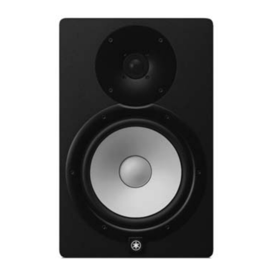
Yamaha Electone HS-8 Instrukcja serwisowa
DISASSEMBLY PROCEDURE(分解手順)
* When you remove binding ties and such, always install as before removal.
※  インシュロックタイなどを外したときは必ず外す前と同じように取付けてください。
1.
Speaker LF (Woofer)
(Time required: About 3 minutes)
1-1
HS8, HS7 :
Remove the six (6) hexagonal socket screws marked
[50A]. The WF ring can then be removed. (Fig. 1)
HS5 :
Remove the four (4) hexagonal socket screws marked
[50A]. The WF ring can then be removed. (Fig. 1)
1-2
HS8, HS7 :
Remove the six (6) screws marked [60]. The speaker LF
(woofer) can then be removed. (Fig. 1)
HS5 :
Remove the four (4) screws marked [60]. The speaker
LF (woofer) can then be removed.(Fig. 1)
*
When installing the speaker LF (woofer), match the
position of the terminal to the direction shown by the
"
" mark.
1-3
Remove the SPOUT connector assembly (red/black)
attached to the speaker LF (woofer) terminal. (Photo 1)
*
The speaker LF (woofer) is heavy. Be careful not to drop it.
*
When you attach/remove the SPOUT connector
assembly to/from the speaker terminal, be sure to
put pressure in the parallel direction. The speaker
terminal will be broken if you put pressure in another
direction.
HS8, HS7 : [60] x 6
: [60] x 4
HS5
HS8, HS7 : [50A] x 6
: [50A] x 4
HS5
Photo 1
(写真1)
Speaker LF (Woofer)
(スピーカ LF (ウー ファー) )
WF ring
(WFリング)
SPOUT connector
assembly (Red)
(SPOUT束線 (赤) )
1. 
スピーカ LF  (ウーファー)
 
(所要時間:約 3 分)
1-1 
HS8, HS7:
 
[50A]の 6 角穴付ネジ 6 本を外し、WF リングを
外します。 (図 1)
 
HS5:
 
[50A]の 6 角穴付ネジ4本を外し、WF リングを
外します。 (図 1)
1-2 
HS8, HS7:
 
[60] のネジ 6 本を外し、 スピーカ LF (ウーファー)
を外します。 (図 1)
 
HS5:
 
[60] のネジ4本を外し、 スピーカ LF (ウーファー)
を外します。 (図 1)
  ※ 
スピーカ LF(ウーファー)を取り付けるときは、端子
の位置を "
1-3 
スピーカ LF  (ウーファー)端子に取り付けられて
いる SPOUT 束線(赤/黒)を外します。 (写真 1)
  ※ 
スピーカ LF(ウーファー)は重量がありますので、落
下させない様に注意してください。
  ※ 
SPOUT  束線をスピーカ端子に取り付けおよび外す際に
は、必ず水平方向に力を加えてください。無理な方向に
力を加えるとスピーカ端子が折れる危険性があります。
Speaker LF (Woofer)
(スピーカ LF (ウー ファー) )
Mark "
" shows terminal direction of speaker LF (woofer).
(        印はスピーカ LF (ウーファー)の端子の方向を示します。
Fig. 1 ( 図1)
SPOUT connector
assembly (Black)
(SPOUT束線 (黒) )
Speaker LF (Woofer)
(スピーカ LF (ウー ファー) )
Photo 1 ( 写真1)
HS8/HS7/HS5
" 印の方向に合わせてください。 (図 1)
7