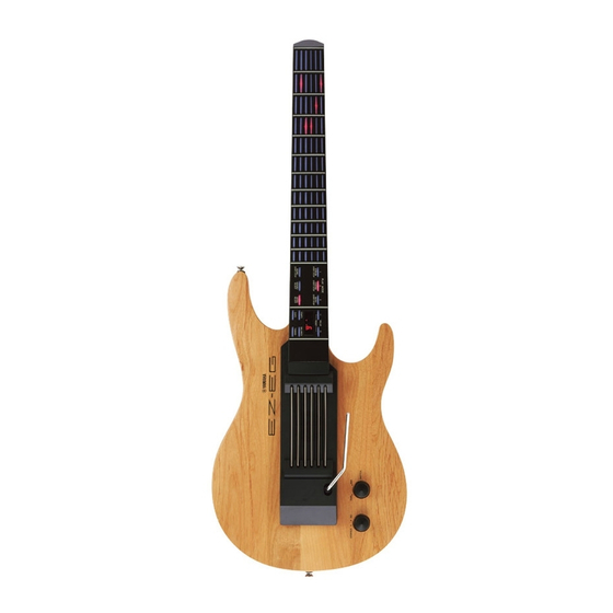
Yamaha EZ-EG Instrukcja serwisowa - Strona 16
Przeglądaj online lub pobierz pdf Instrukcja serwisowa dla Klawiatura elektroniczna Yamaha EZ-EG. Yamaha EZ-EG 34 stron. Song chord chart
Również dla Yamaha EZ-EG: Instrukcja obsługi (2 strony), Krótka instrukcja obsługi (2 strony), Podręcznik uzupełniający (3 strony)

EZ-EG
TEST PROGRAM
1.
Preparation
PA-D09 (AC adaptor) is used.
Set the [MASTER VOLUME] to maximum.
Jigs: Frequency counter, level meter (with JIS-A filter), MIDI cable
Note) Connect a stereo plug to the [PHONES/OUTPUT] jack at 33 ohms.
Please refer to the Internet site below for information and the procedure for transferring data.
http://www.yamahamusicsoft.com/ez-eg/
* The UX16 USB-MIDI interface and song filer (download from the Internet site) are required.
2.
How to enter the Test Mode
While pressing the 1st fret, 2nd fret and 3rd fret of 6th string, turn
the [POWER ON/STANDBY] switch on.
When the test mode is activated, the sign "
the 7-seg. LED display.
3.
Proceeding through the Test Program
1) Select the test item to be executed by pressing the [+] or [-] button.
(Use the [+] button to advance and the [-] button to return.)
2) Select the test item, then press the [STRUM] button to execute testing.
When the test result is OK, press the [STRUM] button and the currently completed test No. will be displayed. The device will
then return to the test item selection mode.
* The dot will be added to the test No. display for the test item that has been completed. (Ex.
When the test result is NG, press the [DEMO] switch to return to the test items for selection.
4.
Test items list
TEST
7-seg. LED for Each Test
No.
1
2
3
4
6
11
13
–
14
15
19
16
" is indicated on
Displays the ROM version.
/
ROM (Program, Wave) versions are displayed alternately on the LED.
Check the ROMs.
or
Checks all the ROMs that are connected to the CPU bus.
Check the RAMs.
or
Checks all the RAMs that are connected to the CPU bus.
Check the WAVE ROMs.
or
Checks the WAVE ROMs that are connected to the CPU bus.
Check the FLASH ROMs.
or
Checks the FLASH ROMs that are connected to the CPU bus. It takes about 3 seconds.
Check the Sound Source (Autoscale).
Outputs the sine wave from C2 to G4. Check the sound by hearing that there is not noise or abnormal
sound.
Check the pitch.
Connect the frequency counter to the [PHONES/OUTPUT] jack (either L or R). (less than 440.0 Hz +/
- 1.76 Hz)
Decline quantity check of the volume.
Connect the level meter to the [PHONES/OUTPUT] jack (L, R). Set the [MATER VOLUME] at MIN
and measure. (33 ohm load)
L, R: less than -70.0 dBm
Check the output level (R) (1 kHz).
Connect the level meter to the [PHONES/OUTPUT] jack (L, R) and measure. (33 ohm load)
L side: -8.0 dBm +/- 2 dB
Disconnect the [PHONES/OUTPUT] jack and then check that only the speakers create sound.
Check the output level (L) (1 kHz).
Connect the level meter to the [PHONES/OUTPUT] jack (L, R) and measure. (33 ohm load)
L side: -8.0 dBm +/- 2 dB
Check the noise.
Connect the level meter to the [PHONES/OUTPUT] jack (L, R) and measure. (33 ohm load)
L, R: less than -75.0 dBm
6th string/1st, 2nd, 3rd fret
Test Function and Judgment criteria
R side: -4.5 dBm +/- 2 dB
R side: -45.0 dBm +/- 2 dB
[POWER ON/STANDBY]
)
