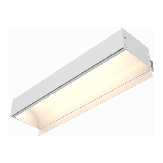
CALI alumLEDs ALS500T-RMW-TB Instrukcja instalacji - Strona 4
Przeglądaj online lub pobierz pdf Instrukcja instalacji dla Oświetlenie zewnętrzne CALI alumLEDs ALS500T-RMW-TB. CALI alumLEDs ALS500T-RMW-TB 16 stron.

1
Do not install ceiling tiles until after installation of luminaires is complete.
Installation area must have at least 10" of overhead space.
2
Install T-Bar ceiling grid. Assemble the grid so there is a continuous edge
around grid for the Ceiling Trim to rest on. Hang the center of the T-Bar 7-5/16"
away from wall stud.
Wall Stud
5/8" Drywall
3
Hang or cut drywall along installation area so it is flush with the ceiling line.
Measure exactly 4" above ceiling line and mark each wall stud in the installation
area. Use a laser level to ensure accurate relation to ceiling line, then draw a
reference line connecting each mark along the wall studs.
Note: Drywallers must hang drywall to the specifications. Only cut if necessary.
Mark Wall Stud
4"
Top of drywall
4
Mark locations along Wall Trim extrusion where it will be mounted to wall studs,
then drill holes as needed and mount to wall studs.
Note: Mount Wall Trim extrusion using at least 1 screw per 2', rounded up.
Mount Wall Trim
CALIFORNIA ACCENT LIGHTING, INC.
2820 E. Gretta Lane, Anaheim, CA 92806
ph. 800.921.CALI (2254) | fx. 714.535.7902 | [email protected] | calilighting.com
© CALI. All rights reserved. CALI reserves the right to make changes or withdraw specifications without prior notice.
Support Wire
T-Bar
Maintain
Continuous Edge
7-5/16"
Ceiling Line
Ceiling Line
ALS500T-RMW-TB
Mounting (Hanging Bracket Assembly ) 1 of 2
5
Determine number of Hanging Brackets required.
Note: Refer to the diagrams on page 10 as a guide.
6
If applicable, assemble Hanging Bracket Arms. Insert Hex Head Bolts through
slots on Hanging Bracket Arms and secure with washers and hex nuts.
Slot
Lock Washer
8-32 x 2"
Hex Head Bolt
7
Mark locations where each Rail Bracket will be installed along reference line.
Align the bottom of the Rail Bracket with the reference line and pre-drill using
proper drill bit for surface and screw size. Each rail must be mounted with a
minimum of two screws. Drill additional holes in Rail Brackets if necessary.
Note: Use 8/32 x 2" Countersink Screw (By others)
Rail Bracket
Countersink Screw
8
Install Hanging Bracket Arms to luminaire by sliding inverted Hex Head Bolts of
Hanging Bracket into the channels pictured below.
Do not slide into any other channels.
9
If applicable, install end caps to ends of runs.
INSTALLATION INSTRUCTIONS
Hanging Bracket Arm
Hex Nut
1 / 29 / 2021 / Rev 2
Page 4 of 16
