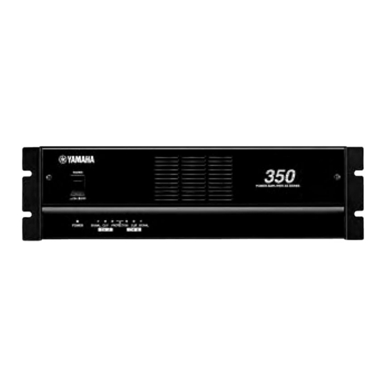
Yamaha XS250 Instrukcja obsługi - Strona 5
Przeglądaj online lub pobierz pdf Instrukcja obsługi dla Wzmacniacz Yamaha XS250. Yamaha XS250 15 stron. Power amplifier
Również dla Yamaha XS250: Instrukcja serwisowa (28 strony)

- 1. Power Amplifier
- 2. Table of Contents
- 3. Controls and Functions
- 3. Front Panel
- 3. Rear Panel
- 3. Speaker Impedance
- 4. Caution for Speaker Connection
- 5. Rack Mounting
- 5. Mounting in an EIA Standard Rack
- 5. Portable Rack Mounting
- 5. Fixed Installation Mounting
- 5. General Specifications
- 6. Specifications
- 6. Block Diagram
- 6. Dimensions
- 7. Troubleshooting
Rear Panel
1
FILTER
CHANNEL B
CHANNEL A
FREQ.
FREQ.
90
90
20
50
50
25
125
125
30
40
25
150
25
150
00
Hz
Hz
CHANNEL B
LOW CUT
LOW CUT
SUB WOOFER
SUB WOOFER
OFF
OFF
INPUT
CHANNEL B
CHANNEL A
(BRIDGE)
(PARALLEL)
1
Frequency controls/Filter select switches (CHAN-
NEL A, B)
These knobs and sliding switches are used to select a
filter type and control the cut-off frequencies respec-
tively. You can select one of the following filter type:
OFF
OFF ........................ Turns the filter off.
SUB WOOFER ...... Turns the low pass filter on.
LOW CUT .............. Turns the high pass (low cut)
If you select "LOW CUT," you can use the frequency
controls to adjust the cut-off frequencies in the range
of 25 Hz to 150 Hz.
50
Note: In BRIDGE mode, only the frequency control
and filter select switch for Channel A are available.
2
3
15
15
20
10
10
25
6
6
30
3
3
40
0
00
0
–dB
–dB
CHANNEL A
MODE
BRIDGE
STEREO
PARALLEL
INPUT
CHANNEL B
CHANNEL A
G
G
5
LOW CUT
SUB WOOFER
(The cut-off frequencies for
the low pass filter are fixed.)
This setting is suitable when
using the unit as an amplifier
for a subwoofer.
filter on. (The cut-off frequen-
cies are variable.)
FREQ.
90
125
25
150
Hz
B-2
4-8 /CHANNEL (STEREO)
–
(BRIDGE)
(PARALLEL)
8-16 (BRIDGE)
6
2
Volume controls (CHANNEL A, B)
These knobs enable you to adjust the output level of
Channels A and B in the range between – dB and
0 dB. In BRIDGE mode, only the volume control for
Channel A is available.
3
STEREO/BRIDGE/PARALLEL switch
This slide switch is used to set the amplifier operating
mode: STEREO, BRIDGE or PARALLEL.
• STEREO mode
In this mode, channels A and B operate independently
(as a conventional stereo amp).
The CHANNEL A input signal will be output from
the CHANNEL A output jacks, and the CHANNEL B
input signal will be output from the CHANNEL B
output jacks.
• BRIDGE mode
In this mode, the CHANNEL A input signal will be
output from the BRIDGE output jacks. In this case,
use the rear panel CHANNEL A volume control to
adjust the volume.
• PARALLEL mode
In this mode, the CHANNEL A input signal will be
output from the output jacks of both channels A and
B. The CHANNEL B input jack is not used. The
CHANNEL A and B volumes can be adjusted
independently.
4
SPEAKERS
CHANNEL
A-2
–
+
+
–
(–)
(+)
BRIDGE
STEREO
PARALLEL
B-1
CHANNEL
A-1
4-8 /CHANNEL (STEREO)
+
+
–
(–)
(+)
8-16 (BRIDGE)
5
