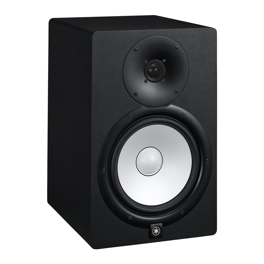
Yamaha HS50M Instrukcja serwisowa - Strona 10
Przeglądaj online lub pobierz pdf Instrukcja serwisowa dla System głośników Yamaha HS50M. Yamaha HS50M 27 stron. Hs series powered monitor speaker
Również dla Yamaha HS50M: Instrukcja obsługi (17 strony), Instrukcja obsługi (16 strony)

HS80M/HS50M
6.
TRANS Circuit Board and Power Trans-
former
(Time required: about 2 minutes)
6-1
Remove the rear panel assembly. (See procedure 3.)
6-2
Remove the four (4) screws marked [130]. The TRANS
circuit board with the power transformer can then be
removed. (Fig. 3)
6-3
Unsolder the power transformer mounting solder (6
locations) and separate the power transformer from
the TRANS circuit board.
*
The power transformer is not a component of the
TRANS circuit board.
7.
AC INLET Circuit Board
(Time required: about 2 minutes)
7-1
Remove the rear panel assembly. (See procedure 3.)
Unsold soldered parts (2 locations) of the power
switch.
7-2
Remove the two (2) screws marked [150]. (Fig. 3)
7-3
Unsold the soldered part of the AC inlet grounding
wire and remove the AC INLET circuit board.
(Photo. 4)
[130]
Fig. 3
[110]: Bind Head Tapping Screw-S 3x10 (WG341400)
[115]: Bonding Tapping Screw-B 3x10 (WH042000)
[130]: Bind Head Tapping Screw-S 4x10 (WG341300)
[150]: Bind Head Screw-S 3x15 (WG341500)
10
LEVEL Knob
AC INLET Circuit Board
AC INLET Circuit Board
[110]
[115]
[150]
HS80M
Power Switch
Power Switch
Solder
Solder
AC Inlet
AC Inlet
Photo. 4
[D]
[D]
[E]
[E]
[F]
[F]
Photo. 5
