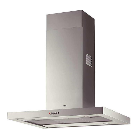
Zanussi ZHC 941 Podręcznik instalacji, użytkowania i konserwacji - Strona 4
Przeglądaj online lub pobierz pdf Podręcznik instalacji, użytkowania i konserwacji dla Okap wentylacyjny Zanussi ZHC 941. Zanussi ZHC 941 11 stron.
Również dla Zanussi ZHC 941: Podręcznik instalacji, użytkowania i konserwacji (11 strony)

○
○
○
○
○
○
○
○
○
○
INSTALLATION
○
○
○
○
○
○
○
○
○
○
This hood is designed for installation over a cooking appliance fitted into a peninsular or
island kitchen cabinet. The hood can be fastened to the ceiling or to a wooden buttress,
using the substantial ceiling fixing system supplied, which is fully adjustable in height.
The hood can be used in either extraction mode (ducted to the outside) or in recirculation
mode (internal recycling).
Safety warnings
• Due to the difficulties which could be experienced when installing this hood, because
of the specific weight of the product, installation should only be carried out by a
qualified or competent technician, in compliance with all the rules concerning the
evacuation of contaminated air. The manufacturer declines all responsibility for any
damage or injury caused as a result of incorrect installation, poor workmanship or
failure to comply with the instructions provided in this manual.
• Do not connect the hood ducting to central heating flues, chimneys, etc..
• The minimum safety distance between the cooker top and the hood is 65 cm.
• Never do flambé cooking under the hood.
• Never leave frying pans unattended during use: overheated fats and oils may ignite.
• If the room in which the hood is to be used contains other non-electric appliances
(such as gas appliances), ensure that there is an adequate supply of air into the room.
When the hood is used in conjunction with other non-electric appliances the negative
pressure in the room must not exceed 0.04 mbar, to prevent fumes from being drawn
back into the room by the hood itself.
Components
The hood is made up of the
following components (fig. 1):
• n.1 hood canopy C, complete with
controls, worktop illumination and
fan unit
• n.1 telescopic frame, comprising:
n.1 upper frame section TS
n.1 lower frame section TI
• n.1 telescopic chimney stack,
comprising:
n.1 upper chimney stack S
n.1 lower chimney stack I
• n.1 deflector D
• n.2 venting grilles G
• n.1 reduction flange Ø 150-120 A
• n.1 additional recirculation spigot
P
• n.2 recirculation clamps F
• n.1 valve V (optional)
• n.1 recirculation spigot R
• n.2 additional recirculation spigots
P1
12
○
○
○
○
○
○
○
○
○
○
○
○
○
○
○
○
○
○
○
○
○
○
○
○
○
○
○
○
○
○
○
○
○
○
○
○
○
○
○
○
○
○
○
○
○
○
○
○
○
○
○
○
○
I
○
○
○
○
○
○
○
○
○
○
○
○
○
○
○
○
○
○
○
○
○
○
○
○
○
○
○
○
○
○
P1
S
R
D
P
G
V
A
C
○
○
○
○
○
○
○
○
○
○
○
○
○
○
○
○
○
○
○
○
○
○
○
○
○
○
TS
T
F
TI
Fig. 1
GB
○
○
○
○
