Clarke CBM240E Instrukcja obsługi i konserwacji - Strona 7
Przeglądaj online lub pobierz pdf Instrukcja obsługi i konserwacji dla Pompa wodna Clarke CBM240E. Clarke CBM240E 17 stron.

The delivery hose should be attached to the outlet adapter which is supplied.
A gate valve may be installed in-line on the delivery side of the pump which
can be set as required to regulate the flow of water. Do not place any such
restriction on the suction side of the pump unless it is an isolator valve in a
gravity fed system.
It is IMPORTANT to note also that this pump should not be operated with the
delivery valve completely closed.
To prevent unnecessary strain or possible distortion to the pump, ensure that
adequate support is provided to the hoses and/or pipes. Remember they will
be considerably heavier when filled with water.
Should sand, chemical or other contaminants come into contact with the
pump, flush through with cold clean water as soon as possible.
Protect the pump and pipework from freezing. The formation of ice may
cause serious damage.
Where the pump is to be a permanent fixture, the fittings to the pump MUST be
flexible, i.e. a short piece of hose should be inserted between rigid metal
pipework and the pump.
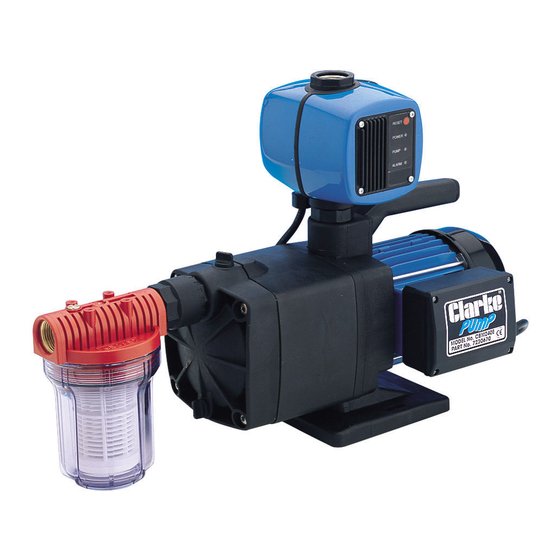
It is strongly recommended that in addition to the coarser foot filter, an inlet
filter should be fitted to prevent the possibility of any foreign body from
entering the pump. This is particularly important in the case of multi- stage
pump such as the CBM240E. A filter specifically designed for all pumps in the
range is available from your CLARKE dealer.
The filter bowl is transparent allowing a visual check as to the condition of the
filter cartridge. The filter cartridge is a washable net type with a rated filtration
of 60 microns, suitable for the efficient removal of suspended particles such as
sand. The filter is NOT designed to filter mud, sludge etc.
This pump is provided with a non-return valve connected to the inlet port.
Screw the non return valve into the inlet port, ensuring the arrow, stamped on
the valve points inwards towards the inlet port. Tighten the valve, BUT DO NOT
OVERTIGHTEN, then screw the filter on to the valve - again DO NOT
OVERTIGHTEN. The filter should hang vertically when completed.
This pump is set up as a BOOSTER Pump by incorporating the CLARKE EPC 1000
HYDROTRONIC UNIT - a computerised electronic device which automatically
switches the pump ON and OFF whenever a tap, or other restriction in the
outlet side of the pump, such as a spray lance etc., is turned ON or OFF.
Please ensure you are thoroughly familiar with the operation of this device by
reading the enclosed leaflet describing its' operation and maintenance,
before you operate the pump. It is important to note that in order for the
hydrotronic unit to operate correctly, the maximum head ABOVE THE outlet
OF THE HYDROTRONIC UNIT, is 14 metres.
7
Parts & Service: 020 8988 7400 / E-mail: [email protected] or [email protected]
